Using the KODAK PROFESSIONAL Device Calibration Software with the KODAK PROFESSIONAL LED II Printers 20P/20R Part No.
©Eastman Kodak Company, 2001 All rights reserved. Contents of this publication may not be reproduced in any form without permission from Eastman Kodak Company.
Contents 1 Calibrating the Printer ...........................................................................................................................1-1 Starting the Device Calibration Software ..............................................................................................1-2 Starting the Calibration Application and Exposing a Test Target .........................................................1-3 Obtaining Densities ..................................................................
Contents Advanced Features of the LED II Calibration Software ......................................................................3-13 Viewing Graphs ............................................................................................................................3-13 Applying a Master Balance (NT Systems Only) ...........................................................................3-18 Sending LUTs .............................................................................................
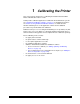
1 Calibrating the Printer This section includes instructions for calibrating the Kodak Professional LED Printers 20P/20R, Generations l and ll. Kodak provides calibration applications for Windows NT and Macintosh systems. See “Installing the Calibration Software” on page 3-1 for installation instructions. See Section 3, Using Additional Calibration Features, for details about the windows and dialog boxes for the application software and for additional procedures not performed with each calibration.
Calibrating the Printer You need to calibrate the printer when you start the system up each day. You also need to calibrate the printer when • you change paper • print quality is questionable • the temperature at the site changes more than 5° F (2.8° C) • if running more than one shift, at the beginning of each shift NOTE: Most windows displayed in this section are from the Windows NT version of the software. The windows for the Macintosh version of the software are similar.
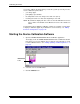
Calibrating the Printer The display shows the LED Calibration Application window. Starting the Calibration Application and Exposing a Test Target IMPORTANT: The settings in the configuration file for the selected device determine some of the actions and messages in this procedure. The configuration file is specific to your lab and its operations. For more information about the configuration file, see “Editing the Device Configuration” on page 3-25. 1. Click Go to start the calibration cycle.
Calibrating the Printer NOTE: Once the application has started, the red stoplight is active and you can click the icon to stop the calibration procedure. If you click the red stoplight icon, the display shows the following dialog box. Otherwise, if the configuration file specifies to Ask if processor is in control, the display shows the Process In Control dialog box. The processor is critical to printer calibration. You can calibrate the printer only if the processor is in control.
Calibrating the Printer 2. Click Yes. The display shows the Choose Start LUT dialog box. NOTE: The highlighted LUT in the dialog box above is the most recent calibration LUT. 3. Click either Load Selected LUT or Load Custom LUT (or Cancel to cancel the calibration process). If you click Load Selected LUT, the system automatically downloads the highlighted LUT to the printer to create a test print.
Calibrating the Printer Obtaining Densities There are three methods for obtaining densities: • from a file • from a densitometer • from a centralized densitometer (NT only and if the Centralized Densitometer application is installed on your network) The contents of the calibration configuration file determine which method you use (see “Editing the Device Configuration” on page 3-25).
Calibrating the Printer Using the Densitometer to Read Densities NOTE: For LED Gen I devices, you read only one neutral strip. Do the following to scan the neutral (gray) patches on the processed test print into the densitometer (refer to your densitometer manual for detailed instructions on using the densitometer): 1. Slide the lever on the densitometer to position 15. Align the edge of the test print with the lever on the densitometer.
Calibrating the Printer Obtaining Densities from the Centralized Densitometer (NT Only) NOTE: For more information about installing and using the Centralized Densitometer Application, see Section 4, Installing and Using the Centralized Densitometer Application. If the configuration settings include obtaining the density data from the centralized densitometer application, the status bar shows a message. 1. Open the Centralized Densitometer Application.
Calibrating the Printer The display shows the window for the Centralized Densitometer Application. 2. Highlight the device. 3. Click Measure (or select Operations->Measure) to measure the target images. 4. At the densitometer, measure the densities (see “Using the Densitometer to Read Densities” on page 1-7). When the densities are measured, the status bar on the Centralized Densitometer Application window shows “Ready.” The density measurements are automatically sent to the LED printer’s host computer.
Calibrating the Printer Completing the Calibration 1. If calibration is in tolerance, the display shows the LUT Attributes dialog box. a. Type a name or comment in the dialog box. The comment you enter will appear on the Send LUT to Printer dialog box to identify the LUT file with a name that is meaningful to you (up to 75 characters). b. Click OK. The new printing LUT is calculated and downloaded. The status bar shows “Calibration Complete.” 2.
Calibrating the Printer If the print densities are out of tolerance, the display shows a graph that allows you to select the type of data and planes that you want to see displayed. a. Click OK.
Calibrating the Printer If specified in the configuration file, the display shows a list of options. Re-read the densitometer values is most useful when the graphs show an unusual plot. Rereading the test print lets you validate the graph, then returns you to the Out of Tolerance dialog box. Iterate again using a newly calculated calibration LUT allows you to keep printing test prints with the newly created LUT without having to save the LUT table.
2 Troubleshooting This section describes the problems that you may occasionally have when using: • the KODAK Device Calibration Software and the Calibration Software for the KODAK PROFESSIONAL LED II Printer • the X-RITE DTP36 Densitometer Calibration Graph The graph below is an indication that the calibration performed was out of tolerance. This may be result from invalid densitometer readings. It is necessary to perform another calibration cycle if you see a graph that looks like the one above.
Troubleshooting Calibration Errors Numeric Calibration Error Codes Code 2-2 Status Message Possible Cause/Subsystem Possible Solution 1 The following file is locked:_filename_. The system is trying to access a file that is currently in use. Close any other applications that may be accessing the file. 2 The following file is protected:_filename_. The system is trying to access a protected file. Change the protections on the file to grant access to the user.
Troubleshooting Code Status Message Possible Cause/Subsystem Possible Solution 11 Error creating DP2 LUT folder A folder of the same name may exist. Change the selected folder name. 101 No response from device:_devicename_. The device is not responding to the system. Verify that the device is connected and on-line. 102 Device not found:_devicename_. The system was trying to access a device that it could not find.
Troubleshooting Code Status Message 110 Unable to perform operation: _operation_ Status Message:_statmsg_ Error Message:_errmsg_. An unknown device error occurred. Use the information in the status message and error message to resolve the device error. 111 There is insufficient memory for the requested operation on device:_devicename_. The application does not have enough memory to complete the operation. Close the other applications and unnecessary windows.
Troubleshooting Code Status Message 117 A software error has been detected by the following device: _devicename_ Error Message: _errmsg_ An error has occurred on the printer. Resolve printer error condition. 118 A SCSI ID for the following device was not found: _devicename_. SCSI driver not found. Reinstall the SCSI driver on host computer. 119 The wrong SCSI ID was specified for the following device: _devicename_. SCSI ID is incorrect. Set the Target SCSI ID to the printer SCSI ID.
Troubleshooting Code 2-6 Status Message Possible Cause/Subsystem Possible Solution 205 Must enter the following field:_field_. The operator left a configuration field blank. Enter information in the blank configuration field. 301 The following key was not found: _key_. • An internal error occurred with the software. • One of the files was edited manually and a key was changed. • Restart the application. • Restore the key to its previous value. • If problem continues, call for service.
Troubleshooting Code Status Message 702 Patch _patch_ has a spread of _spread_ which is out of range _range_. The spread between colors for a given density patch is out of tolerance. Perform another calibration cycle. 703 CalToleranceFile can only be initialized once. An internal error occurred with the software. • Restart the application. • If problem continues, call for service. 704 CalToleranceFile:: initialize must be called first. An internal error occurred with the software.
Troubleshooting Code Status Message 910 Configuration file field:_filename_is invalid. Calibration will be cancelled. The user entered an incorrect value in a configuration file. • Enter the correct value. • Reinstall the application. • If problem continues, call for service. 911 Error_errcode_occurred. Processing stopped. An internal error occurred with the software. Restart the application. 919 Error occurred preparing to handle exit from Kodak Device Calibration.
Troubleshooting Code Status Message Possible Cause/Subsystem Possible Solution 1003 Unable to load default configuration file:_filename_. The default configuration file was deleted or renamed or moved. Restore the file manually or reinstall the software. 1004 Unable to set values in new configuration file. An internal error occurred with the software. Restart the application. 1005 Unable to save configuration file:_filename_.
Troubleshooting Code Status Message Possible Cause/Subsystem Possible Solution 1202 Error:_error_from densitometer. An unexpected error was returned from the densitometer. Calibrate the densitometer. If the problem continues, check the manual for the densitometer. 1203 Error: Number of patches seen by densitometer is incorrect. Unable densities on densitometer. Try adjusting frame counts or reread the density patches on the densitometer.
Troubleshooting Non-Numeric Calibration Error Messages Error Message Possible Cause/Subsystem Possible Solution An underrun error occurred during communications to the following device. • The cable between the printer and the host computer is worn. • One or more of the connections between the printer and the host computer has malfunctioned. • Check that all cables are properly connected.
Troubleshooting Densitometer Errors Code Message <01> BAD_COMMAND The densitometer does not recognize a command. <02> PRM_RANGE_ERROR One or more data or address parameters is out of range. See the command guide for parameter limits. <03> DISPLAY_OVERFLOW_ ERROR An attempt was made to read or write beyond the end of the display. Valid addresses for the display range from 0x00 to 0x20 (0 to 31 decimal).
Troubleshooting Code Message Explanation <11> LAMP_FAILURE The lamp is either burned out or its output is at a level too low for acceptable readings. The densitometer will not read strips until the lamp is replaced and the densitometer is re-calibrated. <12> STRIP_RESTRAINED During calibration, the calibration strip was held or restrained as it passed through the unit. Do not hold the strip as it is reading and make sure the read path is clear of any foreign matter.
Troubleshooting Code Message Explanation <27> BAD_PATCH If the Pattern Recognition comparison window is set to 0 or 1, this error may result when a single patch on the strip is bad due to dirt, smears, creases, etc. (See explanation of CW command for more information.) <30> BAD_STRING_LENGTH A strip definition string received as part of the DS (Define Strip) RCI command did not contain the correct number of characters.
3 Using Additional Calibration Features The topics covered in this section include: • Installing the Calibration Software • An overview of the Kodak Professional Device Calibration Software • Advanced Features of the LED II Calibration Software • Installing the Densitometer IMPORTANT: For the step-by-step procedure to calibrating the printer, see Section 1, Calibrating the Printer.
Using Additional Calibration Features Installation Procedure 1. If you are installing the software from the supplied CD-ROM: a. Place the CD in your CD-ROM drive. b. When the Browser is displayed, select LED Printer. 2. If you are downloading the installation files from the Kodak web site, go to http://www.kodak.com/global/en/service/printers/led2Printer/led2Printer.shtml. 3. Under the heading Product Support, select Drivers, Software and Firmware. 4. Select Calibration Utilities. 5.
Using Additional Calibration Features NOTE: The installation is similar for NT and Macintosh systems. When the instructions say, for example, click Next or Install, the first option is for NT systems and the second is for Macintosh systems. CAUTION: To avoid possible damage, do not connect or disconnect the cable between your host computer and the printer when either device is powered up. 7. Open the installation file (KODAK PROFESSIONAL Device Calibration.exe).
Using Additional Calibration Features 13. Click Next to install the software on your system. The display shows a dialog box for you to designate where to install the calibration software. 14. Either accept the default path and folder or select another path and folder. 15. Click Finish or OK. NOTE: For NT systems, the dialog box gives you the option of reading the readme file associated with your installed applications. 16.
Using Additional Calibration Features About the Kodak Professional Device Calibration Software The Kodak Professional Device Calibration software manages and launches customized calibration software applications, including the calibration software for the LED 20P and 20R printers. Application Window Definitions The window below and the tables that follow define the application window for the KODAK PROFESSIONAL Device Calibration Software.
Using Additional Calibration Features The table below defines the functions and their corresponding icons on the main window of the Device CalibrationSoftware.
Using Additional Calibration Features Starting the Device Calibration Software Load the Calibration Software according to the table below. (If needed, see “Installing the Calibration Software” on page 3-1.) MACINTOSH Systems 1. Open the folder that contains the files for the calibration application. 2. Click the icon for KODAK PROFESSIONAL Device Calibration. NT Systems Select: Eastman Kodak/KPRO Applications/KODAK PROFESSIONAL Device Calibration from the WINDOWS NT Start menu.
Using Additional Calibration Features The display shows the Edit Configuration dialog box with the default settings: 3. Edit the device settings as needed or click Default to refresh the dialog box with the default settings.
Using Additional Calibration Features Adding, Updating, and Deleting Devices You can: • add new printer calibration devices • update the name or SCSI ID (Target ID) of an existing device • delete devices • update the configuration files for devices Adding a Device 1. Click the New icon or select File->New on the Device Calibration window. The display shows the Create a New Device dialog box. 2. Enter the correct device settings. Use a unique identifying word for the device name.
Using Additional Calibration Features A new printer device icon is displayed on the Device Calibration window. NOTE: If an error message is displayed, refer to Section 2, Troubleshooting. Updating a Device To update the device name or the SCSI information for a device: 1. Select the device by clicking once on the device icon on the Device Calibration window. Device icon 2. Click the Edit icon or select File->Edit.
Using Additional Calibration Features The display shows the Update a Device dialog box. 3. Enter the correct device settings. The options for the device settings include: Device Setting Options Device name Enter the name that you want to give to the device. NOTE: The MACINTOSH platform limits the device name to 10 characters. SCSI Host Adapter Adapter ID on host computer SCSI ID The SCSI ID for the device; the default is 5 for the LED Printer 4. Click OK to save (or Cancel to cancel) the changes.
Using Additional Calibration Features Deleting a Device To delete a device and all files associated with the device: 1. Select the device by clicking once on the device icon. Device icon 2. Click the Cut icon or select Edit->Cut. The display shows: 3. Click Yes to delete the device and associated files (or click No to stop the deletion process).
Using Additional Calibration Features Advanced Features of the LED II Calibration Software The Calibration Software for the KODAK PROFESSIONAL LED II Printer 20P/20R provides automated neutral density printer calibration and is designed to be used without assistance from technical experts. The advanced calibration features provided by this product enable you to customize the calibration of the printer.
Using Additional Calibration Features Value Graph 3-14 March 2001
Using Additional Calibration Features Difference Graph March 2001 3-15
Using Additional Calibration Features History Graph 3-16 March 2001
Using Additional Calibration Features To view calibration graphs: 1. From the Device Calibration window, double-click the device for which you want to view graphs. The display shows the LED Calibration Application window. 2. Click the Graphs icon or select View->Graphs. The display shows one of the graphs; typically it is the Value graph. 3. Select the Graph Type that you want to view. When the graph is displayed, select the type of data and planes that you want to see displayed.
Using Additional Calibration Features Applying a Master Balance (NT Systems Only) Master Balance is a method that allows you to temporarily modify printer neutral calibration. This may be desired for customizing a particular job or correcting for a short-term processing shift. It does not replace calibrating the printer. 1. From the Device Calibration window, double-click the device for which you want to perform a master balance. The display shows the LED Calibration Application window. 2.
Using Additional Calibration Features The display shows the Master Balance dialog box. 3. Click and drag the sliders as needed for Density, Red, Green, or Blue balance. For Density, Red, Green, and Blue, 1 unit of change is equal to 0.01 log exposure or 1 color correction (cc) units. For unit changes of less than one, you can type the number directly into the edit box. 4. Click OK to accept the changes (or click Cancel to cancel the master balance).
Using Additional Calibration Features The display shows the Choose Master Balance LUT dialog box. IMPORTANT: In the next step, do not select the default LUT. 5. Select one of the LUTs from the dialog box and click Load Selected LUT or click Load Custom LUT and follow the prompts to load a custom LUT. A new LUT is calculated based on the selected LUT and the input DRGB values. The LUT is downloaded to the printer, overwriting the current LUT.
Using Additional Calibration Features The display shows the LED Calibration Application window. 2. Click the Send LUT icon or select Operations->Send LUT. The display shows the Send LUT to Printer dialog box. 3. Select one of the LUTs from the dialog box and click Load Selected LUT or click Load Custom LUT and follow the prompts to load a custom LUT. The LUT is downloaded to the printer, overwriting the current LUT.
Using Additional Calibration Features Sending Targets The Send Target feature enables you to send any properly formatted target file to the printer without performing a calibration. The target file must contain image data in the format for the Kodak Professional LED II Printer 20P/20R. The format of this file must be raw RGB pixel interleaved. To send a test target to the printer: 1. From the Device Calibration window, double-click the device for which you want to send a test target.
Using Additional Calibration Features The display shows the Send Target to Printer dialog box. (The versions for both NT and MACINTOSH Systems are shown.) NT Systems NOTE: Users of NT systems can click Browse to select another file name. The display shows the Open dialog box. Select the file name, then click Open.
Using Additional Calibration Features MACINTOSH Systems 3. Enter the desired settings and click OK to save the settings (or Cancel to keep the previous settings). The selected test target is sent to the printer.
Using Additional Calibration Features Editing the Device Configuration The Edit Configuration feature allows you to change the printer’s calibration configuration attributes. However, it is recommended that you use the default settings for these attributes for most operations. Edit Configuration consists of a set of six tabs—each with related configuration attributes. There can be only one set of configuration attributes for the printer calibration application at a time.
Using Additional Calibration Features The display shows the LED Calibration Application window. 2. Click the Edit icon or select File->Edit. The display shows the Edit Configuration window with the Procedure tab displayed. 3. To navigate among the tabs, click the tab you want and follow the instructions for updating the information for that tab. IMPORTANT: Whenever you click OK, the software assumes ALL changes to the Edit Configuration are complete and the Edit Configuration window closes.
Using Additional Calibration Features Editing Information on the Procedure Tab The Procedure tab contains general configuration attributes as shown and described below. The values displayed in the example are the default settings. Procedure Attribute Description Graphing Instructs the application when to display the graphs of the data Tolerance Level Indicates whether the level of tolerance is Normal, Loose, Strict, or ColorMetallic Normal. NOTE: ColorMetallic paper requires its own tolerance file.
Using Additional Calibration Features Editing Information on the Density Source Tab The Density Source tab specifies how the calibration application is to receive density data. The values displayed in the example are the default settings. Density Source Attribute Description Density Source Indicates the source (local densitometer or file or, for PC applications only, centralized densitometer application) of the density data.
Using Additional Calibration Features Editing Information on the Aim Tab The Aim tab specifies: • whether the aims used for calibration are Density Aims or Lightness Aims • whether to apply the Channel-Independent Matrix • which table to use if Copyright Detection is functional The values displayed in the example are the default settings. Attribute Description Desired Aim Indicates whether to use Density Aims or Lightness Aims for calibration.
Using Additional Calibration Features Editing Information on the History Tab The History tab specifies information about maintaining calibration history data. The values displayed in the example are the default settings. Attribute Description Keep History For (days) Indicates the number of days that the calibration LUT, print LUT, density data and LUT history information (LED trend data) are to be kept. Information older than the specified number of days will be deleted.
Using Additional Calibration Features Editing Information on the Paper Tab The Paper tab allows you to specify the paper being calibrated. The value displayed in the example is the default setting. Attribute Paper Type Description Select from the list of supported paper types. To edit the configuration information on the Paper tab: 1. Change the Paper Type if needed. 2.
Using Additional Calibration Features Editing Information on the DP2 (NT Systems) or KPIS (MACINTOSH Systems) Tab The DP2 (or for MACINTOSH Systems, KPIS) tab specifies whether to activate DP2 (or KPIS) interoperability, and if so, names the directory and filename designated for the DP2 (or KPIS) information. There are minor differences in the editing of DP2 and KPIS information. Editing DP2 Information (NT Systems) When you click the DP2 tab of the Edit Configuration window, the tab is displayed.
Using Additional Calibration Features Editing KPIS Information (MACINTOSH Systems) If you are using the calibration output files with the KPIS system, it is necessary to activate KPIS and assign a filename and location to the output file. When you click the KPIS tab of the Edit Configuration window, the following tab is displayed. The values in the example are the default settings.
Using Additional Calibration Features To edit the configuration information on the KPIS tab: 1. Click the Activate KPIS checkbox (click again to deactivate). The display shows the Edit Configuration window with the default settings for KPIS Location and KPIS Filename. 2. To change the directory for the KPIS file: a. Click KPIS Location. The display shows the Select KPIS Folder dialog box. b. If needed, browse to find the folder you want. c.
Using Additional Calibration Features The display shows the updated Edit Configuration window with updated File Location of CalDisk:CompositeMachine:Tables:KodakLED. Completing the Edit Configuration When you finish editing the configuration file, click OK to save the attributes. (Click Cancel to exit without saving your changes. MACINTOSH System users: you can click Default at any time to reset the attributes to their factory defaults and then click OK to save the defaults.
Using Additional Calibration Features Creating a Density File for Use with Calibration During calibration, you have the option of obtaining density data from a file or by scanning a processed test target through an X-RITE DTP 36 densitometer. The option is determined by the entry in the device configuration file. If the configuration file is set up to receive density data from a file and you are creating the file: 1. Scan the print into your densitometer. 2.
Using Additional Calibration Features Installing the Densitometer This section describes how to install the X-RITE DTP 36 Densitometer, including changing some of the attributes on the Edit Configuration window to accommodate the densitometer. IMPORTANT: The supported densitometers use a RS-232 interface for communication to the host. Each platform uses different designations to identify the RS-232 ports. To install the densitometer: 1.
Using Additional Calibration Features 3-38 March 2001
4 Installing and Using the Centralized Densitometer Application IMPORTANT: This chapter pertains only to users of WINDOWS NT Systems.
Installing and Using the Centralized Densitometer Application Installation Procedure 1. If you are installing the software from the supplied CD-ROM: a. place the CD in your CD-ROM drive. b. When the display shows the Browser, select LED Printer. 2. If you are downloading the installation files from the Kodak web site, go to http://www.kodak.com/global/en/service/printers/led2Printer/led2Printer.shtml. 3. Under the heading Product Support, select Drivers, Software and Firmware. 4.
Installing and Using the Centralized Densitometer Application 8. After the Welcome screen is displayed, click Next. 9. Read the license agreement. • To accept the terms and continue the installation, click Yes. • Or, to cancel the installation, click No. 10. Read the readme information, then click Next. The display shows a dialog box for choosing the destination location. 11. Either accept the default path and folder or click Browse to select another path and folder.
Installing and Using the Centralized Densitometer Application 13. Click to check the box next to Kodak Professional Device Calibration – Centralized Densitometer and click Next. 14. Click Next to install the software on your system. The display shows the Setup Status dialog box. You do not need to do anything unless you want to Cancel the setup. 15. When the setup is complete, click Finish to restart the host computer. 16.
Installing and Using the Centralized Densitometer Application Using the Centralized Densitometer Application 1. Click the Windows Start button and select Programs -> Eastman Kodak -> KProApplications -> KODAK PROFESSIONAL Device Calibration -> KODAK PROFESSIONAL Centralized Densitometer to open the Centralized Densitometer application. The display shows the Centralized Densitometer Application window.
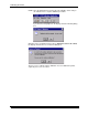
Installing and Using the Centralized Densitometer Application Adding a Printer 1. Click the Add Printer icon or select File->New on the Centralized Densitometer Application window. The display shows the Add New Printer dialog box. 2. Either type a path or click Browse and select a path. Click OK.
Installing and Using the Centralized Densitometer Application The display shows the Centralized Densitometer Application window with the new printer added. Deleting a Printer 1. Highlight the printer you want to delete. 2. Click the Delete icon or select Edit->Delete Printer on the Centralized Densitometer Application window.
Installing and Using the Centralized Densitometer Application The display shows the dialog box below. 3. Click Yes to delete the printer. The selected printer is no longer visible in the Centralized Densitometer Application window.
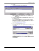
Installing and Using the Centralized Densitometer Application Changing Printer Information 1. Highlight the printer for which you want to change the information (location). 2. Click the Printer Info icon or select Edit->Printer Info on the Centralized Densitometer Application window. The display shows the Update Printer Information dialog box. 3. Change the location for the printer as needed and click OK.
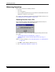
Installing and Using the Centralized Densitometer Application Changing the Densitometer Port You can change the designation of the port on your host computer to which the densitometer is attached. 1. Select Edit->Edit COM Port on the Centralized Densitometer Application window. The display shows the Change Densitometer Port dialog box. 2. Click in the circle next to either COM1 or COM2 and click OK.
Installing and Using the Centralized Densitometer Application If you change the port, a message is displayed on the status bar of the Centralized Densitometer Application window.
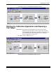
Installing and Using the Centralized Densitometer Application Measuring Densities During a Calibration Cycle IMPORTANT: To use the centralized densitometer application for measuring densities for a calibration cycle, the density source of “centralized densitometer” must have been selected in the edit configuration dialog for the device being calibrated; see “Editing Information on the Density Source Tab” on page 3-28. 1. Open the Centralized Densitometer Application.
Installing and Using the Centralized Densitometer Application Viewing Calibration Graphs The View Graphs feature provides access to the available graphs from the most recently completed calibration for the selected printer. For examples of the graphs, see “Viewing Graphs” beginning on page 3-13. The Value and Difference Graphs reflect the densitometer values that were last read. The History Graph displays the data from completed calibrations.
Installing and Using the Centralized Densitometer Application 4-14 March 2001
EASTMAN KODAK COMPANY Rochester, New York 14653 U.S.A. KODAK CANADA INC. Toronto, Ontario M6M 1V3 Canada Kodak and Kodak Professional are trademarks of Eastman Kodak Company ©Eastman Kodak Company, 2001 Printed in U.S.A.