KODAK PROFESSIONAL HR 500 Plus and Universal Film Scanners P192_0016HC User’s Guide Part No.
© Eastman Kodak Company, 2002 All rights reserved. Contents of this publication may not be reproduced in any form without permission from Eastman Kodak Company.
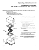
Unpacking Instructions for the KODAK PROFESSIONAL HR 500 Plus and Universal Film Scanners CAUTION: The HR Film Scanner weighs almost 120 lbs (54,5 kg). Two people are needed to safely lift the scanner from the box. The table for the scanner must be: • stable • able to support approximately 120 lbs (54,5 kg) • at least 30 in. (76,2 cm) long x 30 in. (76,2 cm) wide 1. Inspect the box to make sure there is no damage. lid If there is damage, contact the shipping company. 2. Remove the lid from the box. 3.
iv May 2002
Regulatory Information This equipment has been tested and found to comply with the limits for a Class A device, pursuant to part 15 of the FCC rules. These limits are designed to provide reasonable protection against harmful interference when the equipment is operated in a commercial environment. This equipment generates, uses, and can radiate radio frequency energy and, if not installed and used in accordance with the instruction manual, may cause harmful interference to radio communications.
Regulatory Information Cautionary Symbols Hot Surface Symbol CAUTION: Risk of burn. Wait at least 5 minutes for the surface to cool. Fuse Label ! (2) 100-120 V 50/60 Hz 6.3 A / 250 V / F (2) 200-240 V 50/60 Hz 3.15 A / 250 V / T CAUTION: Double pole / neutral fusing. ATTENTION: Double pôle / fusible sur le neutre. ACHTUNG: Zweipolige bzw. Neutralleiter - Sicherung! CAUTION: The scanner uses double pole/neutral fusing.
Regulatory Information Mechanical Hazard Symbol French: Symbole de Danger Mécanique German: Mechanisches Gefahrensymbol CAUTION: Moving parts. Avoid contact. French: ATTENTION: Pièces en mouvement. Ne pas toucher. German: VORSICHT: Bewegliche Teile. Nicht berühren. Warranty Information The following warranty information pertains to equipment that is installed in the United States only.
Regulatory Information Limitations Warranty service is limited to areas within Kodak’s established marketing centers in the contiguous United States, the island of Oahu in Hawaii, and some areas of Alaska. This warranty does not cover circumstances beyond Kodak’s control; it does not cover service or parts for any attachments, accessories, or alterations not marketed by Kodak, nor to correct problems resulting from their use.
Contents Regulatory Information........................................................................................................................... v Cautionary Symbols ....................................................................................................................... vi Warranty Information ..................................................................................................................... vii About This Guide .....................................................
Contents Appendix A: Using the Service and Assembly Module (SAM)............................................................... A-1 Installing the Service and Assembly Module (SAM) Software..................................................... A-2 Using Operations......................................................................................................................... A-3 Appendix B: Ordering Accessories and Supplies ............................................................................
About This Guide This User’s Guide for the KODAK PROFESSIONAL HR 500 Plus Film Scanner and the KODAK PROFESSIONAL HR Universal Scanner includes procedures for operating, maintaining, and troubleshooting the scanner. It also includes an appendix for the optional Long Roll Accessory. This guide is intended for personnel who operate the scanner. It assumes you have a basic knowledge of computer operations and film scanners.
About This Guide xii May 2002
1 Introduction and Overview This chapter includes: • product description • features and benefits • equipment overview • recommended configuration for host computer • film sizes Product Description With the Kodak Professional HR 500 Plus Film Scanner and the Kodak Professional HR Universal Film Scanners, you can quickly generate highresolution digital images from photographic negatives and positives. You can digitally capture images and store them in files up to 128 MB (format dependent) in size.
Introduction and Overview Features and Benefits Features and benefits of the HR 500 Plus and Universal Film Scanners include: 1-2 • high speed and high image quality digital capture • handling of cut negatives, mounted slides, strips, short rolls, and long roll lengths up to 200 feet (61 meters) • compatibility with familiar software, such as – Kodak Professional Digital Print Production Software (DP2) – Kodak Professional HR 500 TWAIN Data Source, which can be used with any TWAIN-compliant program
Introduction and Overview Before You Begin It is important that you know when to calibrate and when to focus the scanner. The table below is a guideline for calibrating and focusing. Focusing can occur as infrequently as when a different film format is scanned or as frequently as every scan.
Introduction and Overview Equipment Overview Front View K-number is visible when this door is open P192_0016HC Rear View Serial Number XXX power switch P192_0019HC 1-4 latch release screw dataplate includes serial number May 2002
Introduction and Overview Recommended Configuration of the Host Computer The scanner is only certified to communicate with Windows NT and Windows 2000 platforms with the following configuration. IMPORTANT: To ensure proper operation of the scanner, use the Ultra-Wide SCSI board provided with the scanner. Built-in SCSI interfaces in some computers may interfere with the provided Ultra-Wide SCSI board. Host Computer Hardware Requirements A SCSI cable connects the host computer to the scanner.
Introduction and Overview Film Sizes Commonly available color negative, color reversal (positive), and black-and-white films are supported by the scanner. Both the HR 500 Plus Film Scanner and the HR Universal Scanner accept these film sizes: • 35 mm – standard perforated format – un-perforated, up to 60 mm frame length • 46 mm, up to 90 mm frame length • 120/220 (62 mm) – 6 x 4.
2 Connecting and Operating the Scanner This chapter gives instructions for: • preparing the host computer • connecting the HR Film Scanner to the host computer • starting up the scanner system • preparing to scan an image • performing a scan • shutting down the scanner Preparing the Host Computer CAUTION: Do not connect power to the scanner. 1. Install the Ultra-Wide SCSI board into the host computer. IMPORTANT: Check the README file on the CD before you install the software. 2.
Connecting and Operating the Scanner Connecting the Scanner CAUTION: Make sure the setting on the AC input module on the back of the scanner agrees with the power source. AC input module P192_0019HC The AC input module is factory-set to 115 V AC (60 Hz) as labeled. The accessories shipped with your scanner include two 220 V fuses (3.15 amps) to convert the scanner to 220 V operation. If your power source is 220 or 230 V AC, verify the configuration of the AC input module.
Connecting and Operating the Scanner Changing the AC Input Voltage Setting and the Fuses If needed, change the AC input voltage setting (voltage selector switch) and both fuses from 115 V AC to 220 V AC operation: 1. Make sure the power cord is removed from the scanner. 115 V locking tab voltage selector switch 2. Insert a straight-blade screwdriver into the locking tab to open the AC input module. 3. Using your fingers (or, if needed, needle-nose pliers), remove the voltage selector switch. 4.
Connecting and Operating the Scanner 115 V 5. Remove the two 115 V AC (6.3 amp) fuses and replace them with the 220 V AC (3.15 amp) fuses. Make sure the arrows are pointing up. fuse arrow fuse in holder 6. Close the AC input module.
Connecting and Operating the Scanner Attaching the Cables CAUTION: In the next step, avoid forcing the cable pins when plugging the cable into the scanner. You need a straight-blade screwdriver to complete the attachment of the cable to the scanner. 1. Attach the Ultra-Wide SCSI cable to the scanner and to the host computer. The host end of the cable contains ferrite beads. 2. Attach the power cable from the scanner to the power source.
Connecting and Operating the Scanner Starting Up the Scanner System NOTE: If the scanner’s power has been on and the scanner has been calibrated, continue with Operating the Scanner beginning on page 2-8. IMPORTANT: Before operating the scanner in a production environment for the first time, validate that the scanner is working properly. See Chapter 3, Validating the Scanner.
Connecting and Operating the Scanner Powering up the Scanner and the Host Computer 1. Turn on the scanner’s power switch. NOTE: The green LED light on the scanner indicates only that AC power is supplied to the scanner, not that the system is ready. Three sets of beeps will sound (first set: one beep; second set: two short beeps; third set: two short, then one long beep). As a visual indicator that the scanner is ready, the scanner lamp lights and remains lit. 2.
Connecting and Operating the Scanner Operating the Scanner Setting the Magnification and Calibrating the Scanner Use your host computer’s scanner software to do this procedure. NOTE: The terminology used in your scanner software may differ from that used in this document. Refer to the software manual’s instructions for performing specific operations such as calibrating the scanner and setting the magnification.
Connecting and Operating the Scanner 2. Make sure the red handle is in the correct position—either negative or positive—for scanning a negative or a mounted slide (positive). IMPORTANT: If you changed the setting of the balance filter, you must calibrate the scanner before continuing. See Setting the Magnification and Calibrating the Scanner on page 2-8.
Connecting and Operating the Scanner Placing a Negative or Mounted Slide in the Film Holder Select the appropriate film holder for the negative or mounted slide you will be scanning. Preparing a Carded Negative IMPORTANT: For best focus, use the film holder that is closest to the size of the opening in the aperture card. 1. Lift the film holder’s magnetic sheet. IMPORTANT: In the next step, the emulsion side must be toward the rear of the scanner. 2.
Connecting and Operating the Scanner Preparing an Uncarded Negative Wear clean, cotton gloves when handling the negative. Illuminate the negative with a light box or hold the negative up to the light to view and align the negative. 1. Identify the emulsion side of the negative. The emulsion side is the dull side of the negative. The printing appears backwards. 2. Select either landscape or portrait orientation. 3. Lift the magnetic sheet.
Connecting and Operating the Scanner Placing the Film Holder in the Scanner 1. Hold the film holder guide so the top handle faces the back of the scanner. Center the film holder between the two rails of the film holder guide. 2. Lower the film holder and let it gently fall into place in the scanner. 3. With your finger, apply pressure to the handle to make sure the film holder is fully seated.
Connecting and Operating the Scanner Focusing With the negative or mounted slide installed in the scanner, use the software installed on your host computer to focus the scanner. IMPORTANT: The need for focusing is partially dependent on the “depth of field.” When the magnification is lower—for example, 0.5—the depth of field is greater and the focus tolerance is high. As the magnification increases, the depth of field and the focus tolerance decrease.
Connecting and Operating the Scanner 2-14 May 2002
3 Validating the Scanner This chapter includes instructions for using the Service and Assembly Module (SAM) and Adobe Photoshop software to validate that the scanner functions properly. NOTES: For more information about using the Service and Assembly module software on the host computer, see Appendix A. Before scanning for the first time, set up a folder (on your host computer) for your work.
Validating the Scanner Starting the SAM Software 1. Open SAM. The Operations window appears with the Mag/Focus tab displayed.
Validating the Scanner 2. Perform a backup of the scanner files: a. Click the Backup & Restore tab. b. Click Backup.
Validating the Scanner Setting the Magnification 1. Click the Mag/Focus tab. 2. Select a Chosen Magnification of 1.00. 3. Click Do Magnification. The lens moves into position. A message appears stating that there is no stored calibration.
Validating the Scanner Calibrating the Scanner 1. Click the Calibrate/Image Processing tab. 2. For the purposes of validating the scanner, make sure the values on the Calibrate/Image Processing tab match the values shown on the sample. The sample is a representation of the default values. 3. Select Shift Image Data Bits Up by Four. 4. Click Calibrate All.
Validating the Scanner Making a Test Scan Before you scan an image, you must identify the area to be scanned and the file that will contain the scanned image. 1. Click the Capture tab. 2. Enter the file information: a. Select Save image to file. b. Click Browse. c. Navigate to the folder for storing your images. d. Click Open to enter the Path.
Validating the Scanner 3. Use the table below only as a starting point for determining Scan Area values. NOTE: Keep the Line Offset (y): at the default value of 0 and keep Pixel Summing at the default value of None. IMPORTANT: The Pixel Offset must be greater than or equal to the first calibrated pixel and # Pixels must be less than or equal to the last calibrated pixel minus the first calibrated pixel. Cut-Gate Film Holders Pixel Offset # Lines 0.50 1033 2484 1460 4.3 1.03 2129 1936 3008 18.
Validating the Scanner Autofocusing 1. Install a negative or mounted slide in the scanner. (See Selecting the Negative or Positive Balancing Filter on page 2-8.) 2. Click the Mag/Focus tab. 3. Click Do AutoFocus.
Validating the Scanner Scanning the Image 1. Click the Capture tab. 2. Click Scan. Checking the Scan 1. On the Capture tab, click Open Image. Adobe Photoshop opens. 2. In Photoshop, enter the required values. a. Enter the Dimensions: • Width = Actual #Pixels when Pixel Summing is None. • Height = Actual #Lines when Pixel Summing is None.
Validating the Scanner b. Enter the Channel information: • • • • Set the Count to 3. Make sure Interleaved is selected. Set Depth to 16 Bits. Set Byte Order to IBM PC. 3. Click OK. After a few seconds, the raw image appears. 4. Select Image>Adjust>Auto Levels. After a few seconds, a clearer image should appear. 5. Select Image>Rotate Canvas>Flip Vertical. NOTE: You may also need to select Image>Rotate Canvas>90° CCW. 6. Check that the image appears as you expected. 7.
4 Maintaining the Equipment This chapter contains procedures to be done by the person who is responsible for maintenance of the HR Film Scanners.
Maintaining the Equipment Cleaning the Light Bar If artifacts appear on your scanned images, clean the light bar. IMPORTANT: Wear white cotton gloves for this procedure to prevent oils and dirt from being absorbed into the microfiber cleaning cloth. 1. Fold a dry, untreated microfiber cleaning cloth so the edge of the cloth is about the thickness of the light bar. NOTE: You can use an e-wipe, manufactured by Photographic Solutions, Inc., instead of a microfiber cleaning cloth. 2.
Maintaining the Equipment lamp Hot Surface symbol leads socket thumbscrews lamp cover P192_0023GC 2. Loosen the thumbscrews on the lamp cover and pull the cover straight out. When you remove the cover, the safety switch is released, removing power to the lamp socket. CAUTION: Wait at least five minutes for the lamp to cool. 3. Push down the lamp release lever. 4. Remove the old lamp from the lamp socket. 5. Fully seat the new lamp in the socket; polarity is not important.
Maintaining the Equipment Replacing the (Round) Balance Filters IMPORTANT: The balance filters are made of glass and are expensive to replace. They are not included in the product warranty or service contract. Use care when handling the balance filters. Wear white cotton gloves for this procedure. It is not necessary to power down the scanner before changing the balance filters. 1. Open the lamp-and-filter-access door (see page 4-2 for the location of the lamp-and-filter-access door).
Maintaining the Equipment 6. Replace the balance filters: a. Remove the 3 screws. b. Remove the filter retainer. c. Remove the old filters and place the new filters in the filter holder. The filters are coated on both sides. It is not important which side faces up or down. d. Secure the filters with the retainer and the 3 screws. 7. Install the filter assembly in the scanner with the balance-filter selection handle in the middle. 8.
Maintaining the Equipment CAUTION: Wait at least five minutes for the lamp to cool. 3. Position the red balance-filter selection handle of the balance-filter assembly in the center. 4. Hold the red handle and pull the assembly straight out from the scanner. 5. Push the IR filter up from below the filter assembly. 6. Clean the IR filter with the camel’s-hair brush or, if needed, replace the IR filter as described in step 7. CAUTION: Use care with the IR filter. It is not secured in place. 7.
Appendix A: Using the Service and Assembly Module (SAM) The Service and Assembly Module (SAM) software performs many of the same functions as other host software. Its primary purpose for users is to validate that your scanner is working correctly and to allow you to perform simple scan functions. There are also service and diagnostics functions that should be used only with the assistance of a Kodak service representative.
Using the Service and Assembly Module (SAM) Installing the Service and Assembly Module (SAM) Software 1. Load the SAM CD. 2. Run setup.exe from the SAM CD. 3. Respond to the prompts in the installation program. You must provide the program location and the name of the program menu item. 4. When installation is complete, reboot your host computer. 5. Remove the CD and store it in a safe place. Backing Up Scanner Files IMPORTANT: It is essential that you back up the scanner files before using SAM. 1.
Using the Service and Assembly Module (SAM) Using Operations If the Operations window does not appear, select View->Operations.
Using the Service and Assembly Module (SAM) IMPORTANT: The Diagnostics, Sensors, Motors & Solenoids, and Transfer tabs are not needed for user functions. Use these tabs only at the request of your Kodak support representative.
Using the Service and Assembly Module (SAM) Performing the Functions on the Mag/Focus Tab IMPORTANT: Magnification Calibration should be done only with the guidance of a Kodak support representative. From the Operations window, click the Mag/Focus tab when you need to set the magnification (position of the lens) or do an autofocus. Setting the Magnification 1. On the Mag/Focus tab, select the Chosen Magnification. The value can be between 0.5 and 2.0.
Using the Service and Assembly Module (SAM) Performing an Autofocus 1. On the Mag/Focus tab, enter the Focus Range. The recommended value is 300. The Range is the initial range of travel used for the CCD and lens, in motor steps. NOTE: To make the focus procedure faster: if you have focused on a given magnification, you can set the Range value to be less than 300. IMPORTANT: Autofocus will be done for the Chosen Magnification.
Using the Service and Assembly Module (SAM) Performing the Functions on the Calibrate/Image Processing Tab From the Operations window, click the Calibrate/Image Processing tab when you need to calibrate the scanner. Setting Image Processing Parameters 1. Select the Data Path. 2. Select the LUT Selected. 3. Select the Dmin Settings. 4. Select the Colors Selected. 5.
Using the Service and Assembly Module (SAM) Calibrating the Scanner IMPORTANT: The CAL (70MM-CAL for HR 500 Plus Film Scanner and 4 x 5 for HR Universal Film Scanner) film holder must be in position in the scanner before you continue. See Placing the Empty Film Holder in the Film Holder Guide on page 2-6. 1. If the values on the Calibrate/Image Processing tab do not match the values shown on the sample on page A-7, change them. The sample is a representation of the default values. 2.
Using the Service and Assembly Module (SAM) Setting the Scan Area To set the Scan Area, enter values for: • # Pixels (valid values range from 1 through 6002); for fastest scanning, enter a value of 1000 • Pixel Offset (valid values range from 0 through 6001) • # Lines (valid values range from 1 through 7464) • Line Offset (valid values range from 0 through 7463) • Pixel Summing (valid values are None, 1:2, and 1:4) NOTE: If you select Pixel Summing of 1:2 or 1:4, use the Actual #Pixels and Actual #Lines fo
Using the Service and Assembly Module (SAM) Using the Miscellaneous Tab Clicking the Miscellaneous tab on the Operations window lets you: • turn the lamp on and off • reset the lamp timer to zero • reboot the scanner • initialize the scanner • set the scanner clock • get scanner usage information • get scanner attributes • get version information Click the appropriate button to perform the corresponding function.
Using the Service and Assembly Module (SAM) Backing Up and Restoring Files From the Operations window, click the Backup & Restore tab when you need to perform either a backup or restore of the scanner files. • Click Backup to back up scanner files. CAUTION: Use Restore only when recommended by a Kodak support person. • May 2002 Click Restore to copy backed up files to the scanner.
Using the Service and Assembly Module (SAM) A-12 May 2002
Appendix B: Ordering Accessories and Supplies Accessories Item Description Manual: Kodak Professional HR 500 Plus Film & HR Universal Film Scanners User’s Guide May 2002 Order Number 6B7198 Kodak Professional HR 500 Scanner Long Roll Accessory 158 5496 Kodak Professional HR 500 35mm Scanner Strip Gate Accessory 843 0316 Kodak Professional HR 500 Scanner 120 Strip Gate Accessory 844 0554 Kodak Professional HR 500/Universal Scanner 35 x 45.
Ordering Accessories and Supplies Available Accessories Item Description Order Number Static Elimination Kit Available from: Holter Associates, Inc. 1170 Pittsford-Victor Road, Pittsford, NY 14534 Phone: (716) 381-7988; Fax: (716) 381-2351 115 V Kit – Static Elimination Kit 2RSM80-115 230 V Kit – Static Elimination Kit 2RSM80-230 Super Film Cleaner or an equivalent cleaner with ionized air and particle transfer rollers (PTR) Super Film Cleaner is available from: Brooke International P.O.
Appendix C: Scanner Specifications Site Specifications AC Power Requirements 1,750 watts peak AC Frequency 50 or 60 Hz AC Phase Single Operating Environment Room temperature: Relative humidity: Ambient light: Altitude: 65 to 80° F (18 to 27° C) 20 to 70% less than 1000 lux; no exposure to direct lighting 7000 feet (2134 m) maximum Scanner Specifications Dimensions and Weight Height: Width: Depth: Weight: Footprint: 15 in. (38,1 cm) 24 in. (61 cm) 30 in.
Scanner Specifications C-2 May 2002
Appendix D: Using the Long Roll Accessory The Kodak Professional HR 500 Film Scanner Long Roll Accessory lets you scan rolls of 35 mm-, 46 mm-, 70 mm-, and 120/220-size edited film. IMPORTANT: The Long Roll Accessory must not be installed when you scan a 4 x 5-in. image.
Using the Long Roll Accessory Installing the Software for the Long Roll Accessory 1. With the PC powered off, power on the scanner. 2. Wait for the series of 3 beeps to sound at the scanner (or for the lamp to illuminate). You must have version 3.0 or higher of SAM (Service and Assembly Module) diagnostic software installed on the host computer and version 3.0 or higher of firmware on your scanner. Downloading the Software and Firmware from KODAK.COM 1. Go to: http://www.kodak.
Using the Long Roll Accessory Upgrading the Scanner’s Firmware Check the Web site (see page D-2) for the most up-to-date instructions. 1. Open SAM and click the Transfer tab on the Operations window. 2. Make sure the File Type is Firmware (W). 3. Click Browse and find the .zip file that you downloaded from KODAK.COM (example: HR500\Px03_000.zip). 4. Click Open. 5. Make sure the Location on the Scanner is Current. 6. Click To Scanner to start the transfer. The transfer takes approximately one minute.
Using the Long Roll Accessory 7. When the transfer is complete, select the Backup & Restore tab and click Backup. 8. When the backup is complete, exit SAM.
Using the Long Roll Accessory Installing or Removing the Long Roll Accessory IMPORTANT: Because of manufacturing tolerances, aperture plates and Long Roll Accessories cannot be interchanged. If your lab has more than one Long Roll Accessory, you may want to use labels with the same colors or numbers to identify aperture plates with the associated Long Roll Accessory. Overview of Parts The parts shown below are shipped with the Long Roll Accessory.
Using the Long Roll Accessory Preparing the Scanner for the Long Roll Accessory You must remove the film holder guide from the scanner before you install the Long Roll Accessory. thumbscrews captive screw film holder guide P192_1539BCA P192_1539BC CAUTION: As indicated in Step 1 below, make sure the scanner is powered OFF. 1. Power off the scanner. 2. Remove the two thumbscrews and loosen the captive screw. 3. Lift the film holder guide up and off the scanner.
Using the Long Roll Accessory CAUTION: Use canned or pressurized air to remove any dust or debris from the connector. 2 mounting screws connector 2 guide pins P192_1540BCA P192_1540BC connector 4. Inspect and remove any dust and debris from the connector. 5. Remove the two mounting screws on each side of the connector. 6. Insert the two guide pins in the holes from which you removed the mounting screws. 7. Tighten the guide pins with a 1/4-in. open-end wrench.
Using the Long Roll Accessory Attaching the Long Roll Accessory to the Scanner CAUTION: Make sure the scanner is powered OFF. 1. Grasp the large rectangular opening to lift and remove the Long Roll Accessory from the shipping box. tension arm toward rear of scanner pressure roller housing toward you rectangular opening pressure roller housing toward you tension arm toward rear of scanner P192_1545BC ends 2. Hold the Long Roll Accessory at the ends and carry it to the scanner. 3.
Using the Long Roll Accessory CAUTION: Avoid hitting the light bar and the safety switch on the scanner. 4. Center the alignment blocks on the Long Roll Accessory between the two dowel pins on the scanner. alignment block dowel pin Long Roll Accessory P192_1542BC 5. Gradually lower the Long Roll Accessory to rest in place on the scanner.
Using the Long Roll Accessory CAUTION: When installing the mounting screws in the next step, use care to avoid • dropping the screws inside the scanner • cross threading the screws mounting screws rear mounting slotted screw screw P192_1543BCA P192_1543BC 6. Install, but do not fully tighten, the rear mounting screw. 7. Hold each of the two mounting screws at the angle of the holes (approximately 45 degrees) and install, but do not tighten, the screws.
Using the Long Roll Accessory Latching and Unlatching the Gate Actuator Be sure you know how to latch and unlatch the gate actuator before installing the aperture plate. The gate actuator must be in the unlatched position for film loading and in the latched position for scanning. Latching the Gate Actuator CAUTION: Be sure the gate actuator is latched before you move the locking arm to the locked position. 1. Pull the gate actuator toward you until the gate “latches” in place. 2.
Using the Long Roll Accessory Installing the Aperture Plate IMPORTANT: To power on the scanner without error, an aperture plate must be installed, latched, and locked. 1. Choose the aperture plate corresponding to the film format you will be scanning. 120/220 lettering on left side P192_1544ACA P192_1544AC 2. Position the aperture plate with the lettering (example: 120/220) visible on the left side. CAUTION: Installing an aperture plate backwards may result in a damaged light bar. 3.
Using the Long Roll Accessory Removing the Long Roll Accessory from the Scanner It may be necessary to remove the Long Roll Accessory from the scanner. CAUTION: Make sure the scanner is powered OFF. To remove the Long Roll Accessory, reverse the installation procedure (see pages D-8 through D-12 for more details): 1. Remove the aperture plate from the Long Roll Accessory. See Latching and Unlatching the Gate Actuator on page D-11. 2. Power off the scanner.
Using the Long Roll Accessory Punch Sensors The punch (data hole) sensors are set up at the factory for negative-type film and require no adjustment during the installation procedure. If you will be scanning film that has a significantly higher or lower D-min from negative film, such as blackand-white film or color positive film, see Determining and Setting the Trigger Points on page D-31.
Using the Long Roll Accessory Adjusting the Core Locator Height on the Spindle The spindles on the Long Roll Accessory have core locators to accommodate different film sizes. detent for 35 mm detent for 46 mm core locator detent for 120/220 mm detent for 70 mm button P192_1548BCA P192_1548BC Push and hold the button to release and position the core locator at the correct detent. Release the button at the detent you want.
Using the Long Roll Accessory Loading and Threading Film IMPORTANT: Careful handling of film is extremely important. Before loading film, clean the film with Super Film Cleaner or an equivalent cleaner that has ionized air and particle transfer rollers (PTR). Use canned air to clean the punch readers before threading film. Before loading film, make sure you have at least 2 feet (.6 meters) of leader at each end of the roll.
Using the Long Roll Accessory Threading the Film 1. Position the film with the data holes down and the emulsion toward the imager. emulsion side data holes P192_1550BCA P192_1550BC You can thread the film from either side of the Long Roll Accessory. 2. Install the film on the spindle. idler arm spindle clamp drive roller aperture P192_1551BCA P192_1551BC 3. Thread the film: a. around the idler arm b. around the drive roller c.
Using the Long Roll Accessory 4. After the film is threaded, pull the gate actuator forward to latch it against the aperture plate. Move the locking arm to the left (locked position). gate actuator CK LO arm in the locked position P192_1552GCA P192_1552GC Setting the Punch Reader Height 1. Open SAM. 2. Click the LAMP button to turn the lamp off. When the lamp is off, it is easier to work in the area of the punch reader.
Using the Long Roll Accessory 3. Select View>Film Controls. 4. Click Load Film. A dialog box appears. 5. Click OK. 6. In preparation for the reader height adjustment, click Fast Fwrd>> to advance the film approximately 10 feet, then click <
Using the Long Roll Accessory Installing the Adjustment Tool 1. Locate the left and right adjusting screws on either side of the aperture plate. 2. Install the height adjustment tool in the right or left adjusting screw. NOTE: You will install the adjusting tool in each adjusting screw; whether it is the left or right screw is determined by which punch reader you adjust first.
Using the Long Roll Accessory Visually Checking the Punch Reader Height 1. Look at the small blue light located in the notch at the top of the punch reader, which is below the pressure rollers and adjacent to the edge of the aperture. The blue light should be in line with the punches in the film. 2. Align the light to the data holes by turning the adjusting screw clockwise to lower the light or counterclockwise to raise the light.
Using the Long Roll Accessory Adjusting the Punch Reader Height Adjust both the left and right reader heights such that the punch reader fully distinguishes between a data hole and film. No specific numbers represent data holes or film, but lower numbers indicate the presence of film and higher numbers indicate the presence of data holes. (See Recording the Highest Numbers on the LEDs on page D-31 for the location of the LED numbers.) For both the left and right readers: 1.
Using the Long Roll Accessory Appendix D-1: Calibrating the Sensor Offsets IMPORTANT: Do this procedure only if you will be using SAM to operate the scanner. Do this procedure twice, once for the left sensor and once for the right sensor. For best visibility, use the largest film format you have. It is not necessary to prepare and load the film twice. Preparing and Loading the Film 1. Create a roll of film with the center of several frames clearly marked. center 2.
Using the Long Roll Accessory Setting the Lens Magnification 1. If the Operations window is not visible in SAM, select View>Operations Controls. 2. Select 1.00 as the Chosen Magnification. 3. Click Do Magnification. 4. Close the Operations window.
Using the Long Roll Accessory Setting the Scan Parameters 1. Select Test>Long Roll Capture from the SAM menu. 2. Set the Scan and Positioning Info. a. Set the #Lines (dy) to 1. b. Set the Line Offset (y) to 0. c. Set Pixel Summing to None. d. Keep the default values for #Pixels (dx), Pixel Offset (x) and X Offset. IMPORTANT: Make sure you close the Test Long Roll Capture window in the next step. 3. Close the Test Long Roll Capture window.
Using the Long Roll Accessory Locating the First Punched Frame 1. On the Film Controls dialog box, click Load First Frm. A dialog box appears. 2. Select the Film Processing Direction: • • If you are calibrating the left sensor offset, select Forward (Left to Right). If you are calibrating the right sensor offset, select Reverse (Right to Left). 3. Type -1 in the First Punch Number field. -1 tells the scanner software to find the first punch (in the specified direction). 4. Click Go.
Using the Long Roll Accessory 5. On the Film Controls dialog box, click Seek Frame. A dialog box appears. 6. Type the Punch Number from the Current Punch on the status bar. 7. Click Go. The Target Punch should equal the Current Punch.
Using the Long Roll Accessory Checking the Alignment and Adjusting the Sensor Offsets 1. Using a flashlight, look from the rear of the aperture to check the alignment of the marked frame with the aperture plate. The center of the frame should line up exactly with the right edge (from the front of the scanner) of the aperture plate. NOTE: The area beyond the aperture plate is not visible when you are checking the alignment.
Using the Long Roll Accessory 2. In SAM, select View>Configurations. CAUTION: Fast Fwrd / Rewind Speed should never be greater than 10. If needed, change the speed to be 10 Inches per sec. or less. As a guideline, the speed should be 10 inches per second if you use 1-inch film cores (the recommended size). The speed should be 8 inches per second if you must use 3/4-inch cores. 3.
Using the Long Roll Accessory 6. If the marked frame is not aligned with the right edge of the aperture plate, select View>Configurations. a. If the film is moving from left to right, change the Left Sensor Offset: If the center of the frame is beyond the right edge of the aperture plate, decrease the Left Sensor Offset. If the center of the frame has not reached the right edge of the aperture plate, increase the Left Sensor Offset. b.
Using the Long Roll Accessory Appendix D-2: Determining and Setting the Trigger Points IMPORTANT: Do this procedure only if you will be scanning film that has a significantly higher or lower D-min from negative film, such as black-and-white film or color positive film. 1. With the PC powered off, power on the scanner. 2. Wait for the series of 3 beeps to sound at the scanner (or for the lamp to illuminate). 3. Power on the PC.
Using the Long Roll Accessory Determining the Left Trigger Point 1. On the Film Controls window of SAM, click Position > to advance the film and determine the “average” low number (indicating the presence of film) on the left LED. An example is 120. 2. Subtract the average low number from the highest number you recorded in step 3 under Recording the Highest Numbers on the LEDs. An example of the highest number is 800. Subtracting 120 from 800 results in 680. 3. Divide the result of step 2 by 4.
Using the Long Roll Accessory Setting the Trigger Points at the Scanner TEACH ADJ SET RUN L MODE D plastic cover P192_1565BCA P192_1565BC 1. On the left side of the scanner: a. Move SET/ADJ/RUN to ADJ. b. Press MODE to increment the number (or press TEACH to decrement the number) to the value you determined to be the left trigger point. c. Move SET/ADJ/RUN to RUN. 2. On the right side of the scanner: a. Move SET/ADJ/RUN to ADJ. b.
Using the Long Roll Accessory Appendix D-3: Maintenance Perform these maintenance procedures at least once a day. 1. In SAM, select View>Film Controls. 2. Click Tension Off and remove film from the gate. It is not necessary to completely unthread the film.
Using the Long Roll Accessory Cleaning the Punch Readers 1. Locate the two punch readers, below the pressure rollers and adjacent to the left and right edges of the aperture. P192_1569BCA P192_1569BC two film punch readers readers 2. Use canned air to clean the left and right punch readers.
Using the Long Roll Accessory Cleaning the Rollers 1. In SAM, select View>Film Controls. 2. On the Film Controls window, click Clean Rollers.
Using the Long Roll Accessory A dialog box appears. 3. Make sure no film is in the gate. Click Yes. The rollers rotate. CAUTION: In the step below, do not use rubbing alcohol. 4. Using a lint-free cloth with 90% or higher isopropyl alcohol, wipe the exposed part of the moving rollers—in the slot at the rear of the housing—from top to bottom. Repeat until the cloth stays clean. roller P192_1568GCA P192_1568GC 5. On the Film Controls window, click Stop.
Using the Long Roll Accessory Appendix D-4: Initial Setup of Sensors IMPORTANT: Do this procedure only if you installed a new sensor or if the sensor setup was accidentally changed. Resetting the Sensors to the Factory Values TEACH ADJ SET RUN L MODE D 1. Move SET/ADJ/RUN to SET. 2. Simultaneously, press and hold TEACH and MODE until nO ? appears (about 5 seconds). TEACH ADJ SET RUN L MODE D NOTE: To cancel resetting the sensors to the factory values, press MODE. 3.
Using the Long Roll Accessory Programming the Sensors for the Long Roll Accessory Power on the scanner. The display on the left sensor will be inverted. Programming the Left Sensor 1. Open the plastic cover on the left display. 2. Make sure the operation mode selector is set to L. NOTE: L means that light triggers high numbers. D means that dark triggers high numbers. TEACH ADJ SET RUN L plastic cover MODE D operation mode selector P192_1555BCA P192_1555BC 3. Move SET/ADJ/RUN to SET. 4.
Using the Long Roll Accessory 6. Change the Detection Function Setting to F HS (high speed): a. Press and hold MODE until F St appears. TEACH ADJ SET RUN L MODE D b. Press TEACH once. F Ld appears. c. Press TEACH again. F HS appears. d. Move SET/ADJ/RUN to RUN. Programming the Right Sensor 1. Open the plastic cover on the right display. 2. Make sure the operation mode selector is set to L. 3. Move SET/ADJ/RUN to SET. 4. Change the Detection Function Setting to F HS: a.
Using the Long Roll Accessory Appendix D-5: Table of Scan Area Values Use the table below only as a starting point for determining scan area values. Long-Roll Film Holders 35 mm doubleperforated 35 mm unperforated 46 mm 6 x 4.5 cm vertical 6 x 6 cm 6 x 7 cm 6 x 9 cm Split 70 mm 70 mm May 2002 Magnification # Pixels Pixel Offset # Lines File Size (MB) .50 1020 2490 1538 4.5 1.03 2102 1949 3168 19.1 2.00 4081 960 6151 71.8 .50 1259 2371 1741 6.3 1.03 2594 1703 3586 26.
Using the Long Roll Accessory Appendix D-6: Film Splicing and Editing Guidelines Follow these guidelines to ensure the scanner correctly reads the data holes. IMPORTANT: When splicing rolls of film, always splice first, then edit. NOTE: The drawings are not to scale. Use care with sticky splice material Because the splice material is sticky, it is possible for residue to remain on the splice material after editing. splice material Ensure that light can shine through all holes.
Index Numerics 4 x 5 film holder for HR Universal Film Scanner 1-6, A-8 70MM-CAL film holder for HR 500 Plus Film Scanner 1-6, A-8 A AC input module 2-2 AC voltage and current draw C-1 AC voltage setting, changing 2-3 to 2-4 accessories, ordering B-1 adjustment tool for Long Roll Accessory, installing D-20 air canned or pressurized 4-1, D-7, D-16, D-35 ionized D-1, D-16 altitude, maximum (operating environment) C-1 ambient light (operating environment) C-1 autofocusing the scanner 3-8, A-5, A-6 B backing
Index K O K-number, on scanner vii, 1-4 Kodak Professional Digital Print Production Software (DP2) 1-3, D-1, D-22 Kodak Professional HR 500 TWAIN Data Source 1-3 operating the scanner 2-8 to 2-13 focusing 2-13 inserting a negative or mounted slide in the scanner 2-10 placing the film holder in the scanner 2-12 preparing an uncarded negative or a mounted slide 2-11 scanning a single frame 2-13 selecting negative or positive balancing filter 2-8 to 2-9 setting the magnification and calibrating the scanner
Index scanner specifications C-1 AC voltage and current draw C-1 clearances, for operation and service of scanner C-1 dimensions and weight C-1 location C-1 power consumption and thermal load C-1 scanning a single frame 2-13 an image using SAM 3-9, A-9 SCSI host adapter 1-5 SCSI interface between host computer and scanner 1-5 sensor offsets on the Long Roll Accessory, calibrating D-23 to D-30 sensors, punch (data hole) on the Long Roll Accessory D-14 serial number on the scanner 1-4 Service and Assembly Mo
Index I-4 May 2002
EASTMAN KODAK COMPANY Rochester, New York 14653 U.S.A. Kodak and Kodak Professional are trademarks of Eastman Kodak Company. © Eastman Kodak Company, 2002 Printed in U.S.A.