6J7611A i600/i700 Series Scanners User’s Guide User’s Guide on Installation CD Guides de l'utilisateur sur le CD d'installation Benutzerhandbücher auf der Installations-CD Guida dell’utente sul CD di installazione Guías de usuario incluidas en el CD de instalación Guias do usuário no CD de instalação Gebruikershandleidingen op installatie-cd Kurulum CD'sindeki Kullanım Kılavuzları Uživatelská pøíruèka na instalaèním disku CD Eastman Kodak Company 343 State Street Rochester, NY 14650 U.S.A. © Kodak, 2010.
Contents 1 Introduction . . . . . . . . . . . . . . . . . . . . . . . . . . . . . . . . . . . . . . . . . . . . . . . . 1-1 Scanner models . . . . . . . . . . . . . . . . . . . . . . . . . . . . . . . . . . . . . . . . . . . . 1-2 New features . . . . . . . . . . . . . . . . . . . . . . . . . . . . . . . . . . . . . . . . . . . . . . . 1-2 Scanner features . . . . . . . . . . . . . . . . . . . . . . . . . . . . . . . . . . . . . . . . . . . . 1-3 Optional accessories . . . . . . . . . . . . . . . . . . . .
Exit deflector . . . . . . . . . . . . . . . . . . . . . . . . . . . . . . . . . . . . . . . . . . . . . . . 3-7 Adjusting the optional short document tray . . . . . . . . . . . . . . . . . . . . . . . . 3-8 Feeding documents using multi-feed detection . . . . . . . . . . . . . . . . . . . . . 3-9 Automatic feeding . . . . . . . . . . . . . . . . . . . . . . . . . . . . . . . . . . . . . . . . . . . 3-9 Continuous feeding . . . . . . . . . . . . . . . . . . . . . . . . . . . . . . . . . . . . . . . . .
1 Introduction This User’s Guide provides information and procedures for the Kodak i600/i700 Series Scanners. The information in this guide is for use with all of the i600/i700 Series Scanners unless otherwise noted. Chapter 1, Introduction — provides general information about the Kodak i600/i700 Series Scanners including a product description, scanner features, safety information and user precautions. Chapter 2, Getting Started — includes specifications and instructions on how to install the scanner.
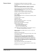
Scanner models • Kodak i610 Scanner is a desktop duplex black and white and grayscale scanner with an automatic document feeder that runs at 80 pages per minute which includes an enhanced printer. • Kodak i620 Scanner is a desktop duplex color scanner with an automatic document feeder that runs at 80 pages per minute which includes an enhanced printer.
Scanner features • Excellent paper handling, image quality, and reliability. • For i600/i700 Series Scanners minimum paper length is 2.5 inches (63.5 mm) • Maximum paper length for i600 Series Scanners is 34 inches (863.6 mm) and i700 Series Scanners 40 inches (1016 mm) • Color or grayscale at the same speed as black and white.* • Includes the Brightness and Contrast Control which allows you to create custom color tables.* • Simultaneous black and white and color image output.
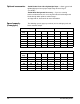
Optional accessories Kodak Feeder Kit for Ultra-Lightweight Paper — allows you to feed lightweight paper from a paper weight range of 25 to 75 g/m2 (7 to 20 lbs). Kodak White Background Accessory — if you are scanning translucent documents, this accessory will reduce black background bleed-through which produces whiter images. See Appendix A, Accessories for more information. Speed/capacity (throughput) The following speeds (pages per minute) are for color/grayscale and black and white output.
Supporting documentation The following documentation is available to support the Kodak i600/ i700 Series Scanners: • Scanning Setup Guide, A-61504 — available in PDF format on the Installation CD. • Quick Tips Guide, A-61501— intended to be used as a quick reference for basic scanner use. • FireWire Installation Information, A-61511 — this installation information is packed with the FireWire cable and should be used to make the required FireWire cable connections.
User precautions Users and their employer need to observe the common sense precautions applicable to the operation of any machinery. These include, but are not limited to, the following: • The scanner weighs 38.6 kg (85 lbs). Use appropriate precautions when relocating the scanner. • Do not wear loose clothing, unbuttoned sleeves, etc. • Do not wear loose jewelry, bracelets, bulky rings, long necklaces, etc. • Hair length should be kept short, using a hair net if needed, or tying long hair up in a bundle.
Taiwan WARNING: This is a Class A product. In a domestic environment this product may cause radio interference in which case the user may be required to take adequate measures. Peoples Republic of China WARNING: This is a Class A product. In a domestic environment this product may cause radio interference in which case the user may be required to take adequate measures.
2 Getting Started Site specifications Place the scanner: • In a clean area with temperature and relative humidity typical of an office environment, • on a stable, level work surface, • within 1.52 metres (5 feet) of an electrical power outlet. IMPORTANT: Only use the scanner indoors in a dry location. For more information about the scanner specifications, refer to Appendix B, Specifications.
Making connections Follow the instructions for installing the IEEE-1394 (FireWire) card and the Kodak driver software before you plug the scanner into the host computer. IMPORTANT: You must install the software on the host computer before you connect the scanner. Installing the IEEE-1394 card in the host computer Install the IEEE-1394 (FireWire) card according to the directions supplied with the IEEE-1394 card. Installing the Kodak Driver software 1. Insert the installation CD in the CD-ROM drive.
Attaching the power cord The Kodak i600/i700 Series Scanner is packed with a set of power cords. 1. Select the power cord which complies with your electrical requirements and attach it. 2. Turn on the scanner and wait until the top green LED is lit indicating the scanner has completed power-up self-test and is idle. Powering up the host computer • Turn the power on to the host computer.
7 Stop/Pause and Start/Resume buttons — Stop/Pause (white with red triangle) button: press once to temporarily pause scanning (the green button can then use used to resume scanning). Press twice to stop scanning (end of job). Start/Resume (green) button: to start scanning. 8 LEDs— illuminate or flash from top to bottom as follows: Illuminates when the power is turned on and the scanner is idle. This indicator will flash if the scanner is in “sleep” or lamp saver mode.
Internal components Rollers Imaging guides Ink blotter strips Separation roller Pre-separation pad Separation roller — provides smooth document feeding of various sizes and textures one document at a time. Ink blotter strips — collects residue from the Enhanced Printer. Imaging guides — the scanner has an upper and lower imaging guide. It is important to keep the imaging guides clean to obtain optimum image quality. CAUTION:Hot surface, avoid contact.
Sensors — the scanner has 3 (ultrasonic) multi-feed detection sensors, 1 (optical) paper path sensor and 1 (optical) paper present sensor. These sensors detect the presence of documents in the elevator tray and documents in the paper path during feeding and imaging. Ultrasonic sensors Paper Path sensor Paper Present sensor Rear view Power cord connection IEEE-1394 connection Retainer clip Power cord connection — provides power to the scanner. The scanner is packed with six power cords.
3 Using the Scanner This chapter provides the following operational procedures: • Turning on/off the scanner • Starting, stopping, pausing and resuming the scanner • Document preparation • Adjusting the side guides and output tray • Scanning documents • Feeding long documents • Automatic, continuous and manual feeding • Calibration Turning the scanner on and off • Press the button on the scanner’s lower right-side (I) to power it up.
Manually pausing and resuming the scanner While scanning documents: • Press the Stop/Pause button on the scanner once to pause scanning. NOTE: Your application may configure the scanner with a transport timeout function which signals an End of Job. If you do not start/ resume scanning before the timeout expires, you cannot continue scanning without restarting the job from the host application. • Press the Start/Resume button on the scanner to restart scanning after it has been paused.
Document preparation Before you begin scanning documents, make certain the documents can be fed through the scanner easily. • A batch of documents to be fed into the scanner must be arranged so the leading edges of all documents are aligned and centered under the feed module; this allows the feeder to introduce documents into the scanner one at a time. • Staples and paper clips in documents may damage the scanner and documents. Remove all staples and paper clips before scanning.
Maximum Document Size: 30.5 x 86 cm (12 x 34 in.). Documents larger than 43 cm (17 in.) require operator assistance. NOTE: The maximum document size for the i700 Series Scanners is 40 inches (1016 mm). Paper inks: All inks on the paper must be dry before scanning is started. This includes: Standard offset printing, Inkjet printer, Thermal transfer, Handwriting inks. Correction Fluids: Liquid Paper®, Tipp-Ex®, Wite-out®, and other similar correction fluids.
Locking the side guides Side guides may be locked into position after they are adjusted. This may be helpful when the placement of print strings is important. If you want to lock the side guides into position, move any documents which may be in the input tray and move the locking switch into the locked position. Adjusting the back of the output tray Different paper types stack differently. The output tray can be set in either one of two positions.
Adjusting the front of the output tray To raise the front of the output tray: 1. Lift the front of the output tray. 2. Swing the height adjustment wire out from underneath the output tray and insert it into the groove on the printer access cover. 3. When finished using the output tray in this position, tuck the height adjustment wire back into position and lower the output tray. Adjusting the output tray for long documents up to 43 cm (17 in.
Adjusting the output tray for documents from 43 cm (17 in.) to 86 cm (34 in.) An output tray document extender is available for scanning documents from 43 cm (17 in.) to 86 cm (34 in.). Contact your Kodak Field Engineer (1-800-3KODAK3) to order the document extender (Part No. 5E4754). 1. Lift the front of the output tray and pull it out of the detent position. 2. Place the output tray in the forward detent position. 3. Gently push down on the left side of the output tray until in snaps into place. 4.
Adjusting the optional short document tray The short document tray is available for scanning smaller documents. This tray is standard with the Kodak i700 Series Scanners. If you have a Kodak i600 Series Scanner, the short document tray can be ordered from Parts Services. See Chapter 5, “Supplies and Consumables” for ordering information. 1. Remove the end stop on the output tray. 2.
Feeding documents using multi-feed detection The scanner has three multi-feed detection sensors. When Multi-feed detection is enabled, adjust the side guides so the documents fully cover at least one sensor. If the document partially covers a sensor, false multi-feeds may occur. Automatic feeding To scan a batch of documents follow the guidelines for size, type, quantity, etc., outlined in the “Document preparation” section.
Continuous feeding Continuous feeding can be used when you want to scan small batches of documents (less than 25). When the scanner is configured for continuous feeding, the elevator tray is raised to a position where approximately 25 documents can be loaded. The elevator tray will remain in this position to allow more documents to be loaded to the bottom of the stack. To continuously feed documents, follow Steps 1 through 5 above.
Feeding documents that require special handling The gap release lever allows you to manually adjust the space between the feed module and separation roller for documents that require special handling; i.e. documents that are badly torn. If you are in doubt about whether a damaged document can be transported through the scanner, use the gap release lever and manually feed the document. Using the scanner in continuous feed mode is recommended when handling special documents. 1.
Image calibration Use the calibration target provided with your scanner. Be sure to use a good, clean calibration target. Additional calibration targets can be ordered. See Chapter 5, “Supplies and accessories” for ordering information. NOTE: The screens shown in this section are for the TWAIN Datasource. The screens displayed on your system may be different. 1. Open the pod and clean the imaging guides. Refer to the maintenance procedures in Chapter 5. 2.
7. Click the Setup icon to access the main Kodak Scanner window. 8. Click Settings. The following screen will be displayed. 9. Click Device.
The following screen will be displayed. 10. Click Diagnostics. The following screen will be displayed. 11. Click Calibrate. 12. Select Image. Calibration begins. A confirmation box is displayed when calibration is complete. 13. Click OK.
NOTE: If calibration fails, check the Operator Log for details. See Chapter 6, “Accessing the Operator Log” for more information. You must wait at least 90 seconds before calibrating again. Ultrasonics calibration Use only an A4 size / 75-80 g/m2 or lettersize / 20 lb. bond paper to perform an Ultrasonics calibration. NOTE: The screens shown in this section are for the TWAIN Datasource. The screens displayed on your system may be different. 1. Center the side guides in the elevator tray and output tray.
4 The Enhanced Printer This chapter provides instructions for using the Enhanced Printer. The following information and procedures can be found in this chapter: • Overview information about the Enhanced Printer, including information about print fields and printer specifications. • Setting horizontal printer positions. • Replacing the ink cartridge and ink blotter strips. NOTE: More detailed information on the Enhanced Printer can be found in the Scanning Setup Guide, A-61504.
Printer specifications Characteristic 4-2 Description Maximum lines 1 Maximum characters 40 Print locations (horizontal) 8 front manually set, Print locations (vertical) Set by capture software application Print orientation 0, 90, 180 or 270 degrees Font size 2 selectable, Bold or Normal NOTE: Not all languages can support a Bold font based on the complexity of the characters, such as half-width Katakana.
Accessing the Enhanced Printer When changing the ink cartridge, setting printer positions or replacing the ink cartridge carrier, you will need to access the Enhanced Printer. 1. Remove the output tray. 2. Open the printer access cover. 3. Do the function you want to perform (i.e., change ink cartridge, change the printer position, etc.). 4. Close the printer access cover and reinstall the output tray.
Changing the printer position There are 8 print positions for the printer. Make sure the printer is in the correct position for your documents. 1. Remove the output tray and open the printer access cover. 2. Locate the printer position slots. 3. Determine which printing position is suitable for your printing needs. 4. Remove the ink cartridge carrier from the current print position and place it in the desired position.
4. Remove the ink cartridge from the ink cartridge carrier. 5. Insert a new ink cartridge into the ink cartridge carrier and close to tab to secure it in place. 6. Place the ink cartridge carrier into the desired print position. 7. Close the printer access cover and reinstall the output tray. 8. Run a print test.
Replacing the blotter strips Blotter strips collect ink overflow. They should be replaced when there is a build-up of ink. Replacement blotter strips may be purchased through your supplier. 1. Open the pod. 2. Locate the two ink blotter strips. Ink blotter strips 3. Carefully pull the blotter strip(s) off the transport. You can replace one or both of the strips as necessary. 4. Discard the soiled strip(s) 5. Peel the backing away from a new blotter strip.
6. Align the blotter strip in the transport channel. Be sure it is properly aligned before pressing the adhesive side into the channel. 7. Press the blotter strip firmly into the channel. 8. Repeat Steps 5 - 7 for the other blotter strip, if necessary. 9. Close the pod. Replacing the ink cartridge carrier Under normal conditions, the ink cartridge carrier should not need to be replaced.
4. Remove the ink cartridge if one is present. 5. Squeeze the metal strips on the connector and pull the connector away from the ink cartridge carrier. 6. Push the connector firmly into a new ink cartridge carrier. 7. Replace the ink cartridge and close the tab to secure it in place. 8. Place the ink cartridge carrier into the desired print position. 9. Close the printer access cover and reinstall the output tray.
5 Maintenance This chapter provides: • a cleaning frequency chart • a list of cleaning tools and materials • a list of supplies and accessories • cleaning procedures for the scanner • replacement procedures for parts that are customer-replaceable IMPORTANT: Scanner components marked with a green tab indicate operator-accessible parts. Cleaning your scanner and preventative maintenance on a regular basis is required to ensure the best possible image quality.
Cleaning frequency chart A recommended cleaning sequence includes vacuuming the scanner transport, cleaning the residue from the feed module, separation roller or drive rollers and cleaning the imaging guides. Use the chart below as a guide to how frequently you should clean your scanner.
Supplies and accessories Contact your scanner supplier to order supplies. Item CAT No.
Cleaning procedure Follow the cleaning procedure below to ensure the best scanner performance and image quality. Cleaning the output tray and elevator area 1. Power down the scanner and unplug it from the wall receptacle. 2. Remove the output tray. 3. Thoroughly vacuum the output tray area and the input area (elevator) using a brush attachment of a vacuum cleaner. Opening the pod 4. Push up on the pod release lever and open the pod.
Cleaning the drive rollers 5. Manually rotate and wipe the NFR and drive rollers with a roller cleaning pad. IMPORTANT: The roller cleaning pad contains sodium lauryl ether sulfate and sodium silicate which can cause eye irritation. Refer to the MSDS for more information. Wash hands with soap and water after performing maintenance procedures. 6. Dry the rollers with a lint-free cloth. Cleaning the separation roller tires 7. Pull the separation pad holder forward and remove the separation roller. 8.
10. Reinstall the separation roller. Cleaning the feed module tires 11. Lift up the printer access cover. 12. Push the release lever down (located underneath the printer access cover) to release and remove the feed module. 13. Manually rotate and wipe the feed module tires with a roller cleaning pad. For best results wipe parallel to the ribs in order to remove any residue between the ribs. 14. Inspect the tires. If the tires show signs of wear or damage, replace the feed module tires.
15. Reinstall the feed module by aligning the pins, fitting it into position and pulling up on the release lever to lock it into place. Verify that the feed module is securely in place and moves freely after you install it. Align these areas 16. Close the printer access cover.
Cleaning the scanner transport area 17.
Cleaning the background strips 18. Using the green tabs pull off the upper and lower background strips and set them aside. Lower strip Upper strip 19. Vacuum the areas where the background strips are adhered to. 20. Reinstall the upper and lower background strips. Cleaning the imaging guides 21. Turn the screw on each end of the upper imaging guide, remove it from its position and set it aside Lower imaging guide IMPORTANT:Allow 5 minutes for lamps to cool. 22.
23. Carefully vacuum the areas between the lamps (both upper and lower), then use a Staticide wipe to thoroughly clean the glass dust plate between the lamps. 24. Clean the imaging guides thoroughly with a Staticide wipe. IMPORTANT: Staticide wipes contain isopropanol which can cause eye irritation and dry skin. Wash your hands with soap and water after performing maintenance procedures. Refer to the MSDS for more information. 25. Reinstall the upper and lower imaging guides.
Running a transport cleaning sheet 1. Place a transport cleaning sheet in the elevator tray in landscape orientation. 2. Open the Scan Validation Tool by selecting Start>Programs> Kodak>Document Imaging>Scan Validation Tool. The Scan Validation Tool dialog box will be displayed. 3. Select TWAIN (or ISIS) for the Driver Types and Kodak Scanner: i600 or Kodak Scanner: i700 as the Driver and click OK. The Scan Validation Tool dialog box will be displayed. 4. If Saved images to file is checked, uncheck it. 5.
Replacement procedures This section provides procedures for replacing the following parts. Use the list below as a guideline for frequency of replacement. • Feed Module tires and Separation Roller tires — tire life will vary depending upon paper types, environment and cleanliness. Nominal tire life will be approximately 500,000 documents; results will vary. Degradation of feeder performance, multiple feeds, stoppages, etc. indicate a need to change tires.
4. Push down on the release lever (located underneath the printer access cover) to release and remove the feed module. 5. If you are just replacing the feed module: • Insert the new feed module by aligning the pins, fitting it into position and pulling up on the release lever to lock it into place. Verify that the feed module is securely in place and moves freely after you install it. • Close the pod and the printer access cover. • Reinstall the output tray.
If you want to replace the tires, proceed as follows: 6. With one hand, press the locking tabs (one on each side) while holding the bottom housing with the other hand, pull the upper housing up and away from the rollers. Locking tab 7. Remove one core assembly. 8. Replace each tire by sliding the tire off the core. Core assembly 9. Install each new tire by gently pulling it over the core. IMPORTANT:Do not overstretch the tire; it may tear. 10. Replace the core assembly in the feed module. 11.
12. Align the tabs on the upper housing with the slots on the lower housing. Locking tab Slot 13. Press the upper and lower housings together until they snap into place. 14. Reinstall the feed module by aligning the pins, fitting it into position and pulling up on the release lever to lock it into place. Verify that the feed module is securely in place and moves freely after you install it. Align these areas 15. Close the pod. 16. Close the printer access cover. 17. Reinstall the output tray.
Replacing the separation roller or separation roller tires 1. Open the pod. 2. Pull the separation pad holder forward and remove the separation roller. If you want to replace the separation roller, do Steps 3 and 4. If you want to replace the separation roller tires, go to Step 5. 3. Insert the new separation roller. Be sure to line up the slots on the separation roller with the holders. 4. Push the separation roller holder back in place and close the pod. To replace the tires: 5.
Replacing the preseparation pad Change the pre-separation pad when the frequency of double-fed documents increases. 1. Open the pod. 2. Remove the pre-separation pad. 3. Install the new pre-separation pad. Be sure it snaps into place. 4. Close the pod. Replacing the imaging guides The imaging guides should be replaced when they are heavily scratched and defects show in the image. NOTE: Handle the imaging guides carefully as to not put fingerprints on the guides. 1. Open the pod. 2.
6 Troubleshooting This chapter provides: • A description of the indicator lights located on the front of the scanner. • Information about accessing the Operator Log. • A problem solving chart. • A message listing of possible errors you may encounter while using the scanner. Indicator lights There are four indicator lights on the front of the scanner.
Led display Description Scanner is in sleep mode and has detected a hardware error. Cycle power on the scanner. If the condition persists, see the Operator Log for details. If the condition cannot be cleared, call Service. Scanner warm-up sequence. Scanner is enabled. Start/Resume and Stop/Pause buttons are available. Scanner is enabled and scanning is allowed. Start/Resume and Stop/Pause buttons are available, however a warning condition has been detected. See the Operator Log for details. (e.g.
Accessing the Operator Log The Operator Log is accessed through the Scan Validation Tool. 1. Select Start>Programs>Kodak>Document Imaging>Scan Validation Tool. 2. From the Driver Types box, select TWAIN. 3. Open the Scan Validation Tool. 4. Select Kodak Scanner: i600 or Kodak Scanner: i700. The main Kodak Scanner window will be displayed.. 5. Click the Setup icon to access the main Kodak Scanner window..
6. Click Settings. The following screen will be displayed. Click Device.The following screen will be displayed.
7. Click Diagnostics. The following screen will be displayed. 8. Click the Logs tab. 9. From the drop down box, select Operator to display the Operator log. The most current log entries are displayed at the top of the list. See the following Message Listing for an explanation of the error condition.
i600 Series Scanners Message listing Messages Following is an alphabetic list of messages and corrective actions you can take if one of the following messages is encountered. ID# Operator Message Background accessory changed while powered up 381 The Background Accessory was changed while the scanner was powered on. • Turn the power off to the scanner, wait a few seconds and power the scanner back on. • If you get this message and you did not change the Background Accessory, clean the scanner.
Messages Clean upper imaging guide ID# Operator Message 293, 304 The upper imaging guide is dirty or there may be a small piece of paper in the imaging guide area. • Clean the imaging guides. See Chapter 5, Maintenance for procedures. Document count exceeded maximum value 124 The document counter is larger than the maximum configured value. • Reconfigure the scanner to allow a larger value for the document counter. Refeed the document set. Document too dark to deskew 143 Informational message.
Messages ID# Operator Message Input elevator too full, feed module missing or broken 297 • There is too much paper in the elevator tray and it is holding the feed module up. The maximum elevator tray capacity is 500 sheets. Remove some documents from the elevator tray. • The feed module is not installed properly. See Chapter 5, Maintenance, for correct installation procedures. • If the problem persists, call Service.
Messages Paused waiting for host ID# Operator Message 1, 48 The feeder has stopped and the transport is still running because the scanner’s internal image buffer is almost full. Processing will automatically resume after the capture software application has successfully retrieved enough images to allow the scanner to continue. • Be sure your host computer meets the recommended specifications to avoid this condition.
Messages ID# Operator Message UDDS calibration failed 333 The UDDS calibration failed. • Be sure you are using the correct ultrasonics calibration target. See Chapter 3, “Calibrating the scanner”. • Clean the sensors and try again. • If the problem persists, call Service. UDDS calibration succeeded 332 Informational message. The scanner ultrasonics has been successfully calibrated. UDDS is not calibrated 21 • Perform an Ultrasonics calibration.
i600 Series Scanners Numerical Message listing Use the following numeric listing to quickly find an error. Use the previous Message Listing chart for details and actions regarding the error condition.
ID# Operator Message 184 Cannot calibrate with white background 260 No paper in input elevator 280 Lamps ready for scanning 281 Printer bitmap font in use 282 Ink cartridge not installed 293 Clean upper imaging guide 294 Clean lower imaging guide 297 Input elevator too full, feed module missing or broken 319 Cable unplugged 331 Calibration failed 332 UDDS calibration succeeded 333 UDDS calibration failed 336 Transport timeout 337 Requested pages scanned 355 Lamps timed out 35
i700 Series Scanners Message listing Messages Following is an alphabetic list of messages and corrective actions you can take if one of the following messages is encountered ID# Operator Message Background accessory changed while powered up 381 The Background Accessory was changed while the scanner was powered on. • Turn the power off to the scanner, wait a few seconds and power the scanner back on. • If you get this message and you did not change the Background Accessory, clean the scanner.
Messages Clean upper imaging guide ID# Operator Message 293, 304 The upper imaging guide is dirty or there may be a small piece of paper in the imaging guide area. • Clean the imaging guides. See Chapter 5, Maintenance for procedures. Document count exceeded maximum value 124 The document counter is larger than the maximum configured value. • Reconfigure the scanner to allow a larger value for the document counter. Refeed the document set. Document too dark to deskew 143 Informational message.
Messages ID# Operator Message Input elevator too full, feed module missing or broken 297 • There is too much paper in the elevator tray and it is holding the feed module up. The maximum elevator tray capacity is 500 sheets. Remove some documents from the elevator tray. • The feed module is not installed properly. See Chapter 5, Maintenance, for correct installation procedures. • If the problem persists, call Service.
Messages Paused waiting for host ID# Operator Message 1, 48 The feeder has stopped and the transport is still running because the scanner’s internal image buffer is almost full. Processing will automatically resume after the capture software application has successfully retrieved enough images to allow the scanner to continue. • Be sure your host computer meets the recommended specifications to avoid this condition.
Messages ID# Operator Message UDDS calibration failed 333 The UDDS calibration failed. • Be sure you are using the correct ultrasonics calibration target. See Chapter 3, “Calibrating the scanner”. • Clean the sensors and try again. • If the problem persists, call Service. UDDS calibration succeeded 332 Informational message. The scanner ultrasonics has been successfully calibrated. UDDS is not calibrated 21 • Perform an Ultrasonics calibration.
i700 Series Scanners Numerical Message listing Use the following numeric listing to quickly find an error. Use the previous Message Listing chart for details and actions regarding the error condition.
ID# Operator Message 184 Cannot calibrate with white background 260 No paper in input elevator 280 Lamps ready for scanning 281 Printer bitmap font in use 282 Ink cartridge not installed 293 Clean upper imaging guide 294 Clean lower imaging guide 297 Input elevator too full, feed module missing or broken 319 Cable unplugged 331 Calibration failed 332 UDDS calibration succeeded 333 UDDS calibration failed 336 Transport timeout 337 Requested pages scanned 355 Lamps timed out 35
Problem solving Problem Scanner does not power on Use the chart below as a guide to check possible solutions to problems you may encounter when using the Kodak i600/i700 Series Scanners. Possible Solution Make sure that: • the power cord is plugged securely into the receptacle in the back of the scanner. • the wall outlet is not defective (call a licensed electrician). • the power switch is on.
Problem Possible Solution Long documents are not feeding or are Make sure that: jamming • the elevator tray extender is pulled out to provide support for long documents. • the output tray is adjusted for the length of the documents being scanned. • the output tray is installed properly. Roller marks appear on the documents Clean the feed module rollers, separation rollers and transport rollers.
Appendix A Accessories This appendix provides a description for the accessories that are available for use the Kodak i600/i700 Series Scanners. • Kodak Feeder Kit for Ultra-Lightweight Paper — allows you to feed lightweight paper from a paper weight range of 25 g/m2 to 75 g/m2 kg (7 to 20 lbs). CAT No. 896 5279 • Kodak White Background Accessory — if you are scanning translucent documents, this accessory will reduce black background bleed-through while scanning which produces whiter documents. CAT No.
Appendix B Specifications Scanner Type/Speed • i610 Scanner: duplex black and white and grayscale scanner with an automatic document feeder including an enhanced printer, 80 pages per minute (landscape) • i620 Scanner: duplex color scanner with an automatic document feeder including an enhanced printer, 80 pages per minute (landscape) • i640 Scanner: duplex color scanner with an automatic document feeder including an enhanced printer, 100 pages per minute (landscape) • i660 Scanner: duplex color scanner wi
6J7611A i600/i700 Series Scanners User’s Guide User’s Guide on Installation CD Guides de l'utilisateur sur le CD d'installation Benutzerhandbücher auf der Installations-CD Guida dell’utente sul CD di installazione Guías de usuario incluidas en el CD de instalación Guias do usuário no CD de instalação Gebruikershandleidingen op installatie-cd Kurulum CD'sindeki Kullanım Kılavuzları Uživatelská pøíruèka na instalaèním disku CD Eastman Kodak Company 343 State Street Rochester, NY 14650 U.S.A. © Kodak, 2010.