Operator's Manual KODAK IMAGELINK Printer 7 BUSINESS IMAGING SYSTEMS A-62032 Part No.
The Kodak Imagelink Printer 7, CAT No. 887 9405, with the Kodak Imagelink Printer 7 Paper Supply, CAT No. 859 1943, the Kodak Imagelink Printer 7 Sorter, CAT No. 864 6754, and the Kodak Imagelink Printer 7 Sorter Interface, CAT No. 199 7964, are in conformance with the following standards and bear therefore a CE mark: EN 55022 Class B/1987 EN 50082-1/1992 EN 60555-2/1987 EN 60950/1993 following the provisions of the applicable directives: 89/336/EEC and amendments 73/23/EEC and amendments.
Warning and safety information Locate the printer in a well-ventilated room. A negligible amount of ozone is generated during normal operation of this printer. An unpleasant odor may, however, be created in poorly ventilated rooms during extensive printer operations. For a comfortable, healthy, and safe operating environment, it is recommended that the room be well-ventilated. A dedicated electrical socket-outlet shall be installed near the printer and shall be easily accessible.
Section 1 Overview Introduction We are pleased that you have purchased the Kodak Imagelink Printer 7. We feel confident that you will find your new laser printer more than adequate to meet your printing needs. In order to make the best use of the printer, we recommend that you read the information in this manual carefully and follow the instructions contained herein.
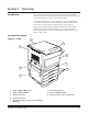
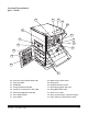
Location/Description of parts—Back 12 11 13 10 14 15 9 16 19 17 18 9. Paper Supply Cabinet Right Cover 10. Paper Exit Tray 15. Paper Supply Cabinet Rear Cover 16. Dataplate 11. Printer Right Cover 12. Printer Cable Interface Socket 17. Circuit Breaker 18. Power Cord Socket 13. Printer Rear Cover 19. Adjustable Feet 14.
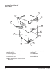
Location/Description of parts—Inside 26 27 28 29 30 25 31 24 32 33 23 34 22 21 20 35 20. Vertical Transport Roller Knob (M6) 21. Separator Roller 28. Drum Charge Ozone Filter 29. Fusing Unit 22. Feed Roller 23. Transport Roller Knob (M5) 30. Mechanical Print Counter 31. Electrophotographic (EP) Unit 24. Transport Section Release Plate (M4) 32. Fusing Roller Knob (M1) 25. Synchronizing Roller Knob (M3) 26. Toner Bottle Holder 33. Release Lever (M2) 34.
Section 2 Operation Turning the printer on and off Check that the power cord has been connected to the printer and outlet; turn the power ON/OFF switch to its right side ( side) to turn the power on. Turn the power ON/OFF switch to its left side ( power off. side) to turn the The operation panel contains the Printer Status and Error Code displays, and the Test controls.
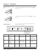
Loading paper This laser printer supplies paper to the printer by feeding paper into the unit automatically from one of four universal cassettes. Universal cassette The universal cassette can be used to feed the following paper sizes: A3T, B4T, A4T/Y, A5T, B5T/Y, B6T, LedgerT, LegalT, LetterT/Y, ExecutiveT/Y, InvoiceT, 7 x 8 1⁄2". (T means lengthwise feeding and Y means crosswise feeding.) See Appendix A for more information on paper sizes.
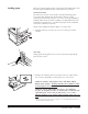
3. While holding the cassette, depress and spread the front paper guide wider than the paper size to be used. 4. Slide the green resin plate of the right paper guide toward the right side wider than the paper size to be used. NOTE: Be sure to slide the resin plate and not to hold the lever part, as that may bend it. 5. When you load the ledgerT size paper, slide the right paper guide all the way to the right side and remove the lever by depressing it from the both sides.
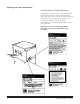
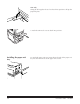
USA only Swing the lift-up plate release lever back into position to lift up the paper lift plate. 7. Push the universal cassette back into position. Installing the paper exit tray 2-4 To attach the paper exit tray, insert the two hooks of the paper exit tray into the lower holes of the paper exit section.
Clearing paper jams When a paper jam occurs, remove the paper jammed in each section according to the following procedures. Inside the paper supply cabinet (J1 error) 1. Pull the paper cassettes out from the printer and check if the paper in each cassette is stored correctly. If the paper is not stored correctly, remove the jammed piece of paper. Push the paper cassettes back into position. 2. Open the paper supply cabinet door (C2) and remove any paper. Close the paper supply cabinet door.
Inside the printer (J2 or J3 error) 1. Open the front cover and release lever M2 to unlock the vacuum unit. M2 M5 2. Open the transport section release plate (M4). Remove the paper by rotating the transport roller knob (M5) or the synchronizing roller knob (M3) in the direction of the arrow. M4 M3 3. When the leading edge of jammed paper has reached into the fusing unit, remove the paper toward the inside of the printer while depressing and rotating the roller knob (M1) in the direction of the arrow.
Inside the sorter and sorter interface unit (J4 or J6 error) Lock Release Lever 1. Press the lock release lever of the 20-bin sorter to open the sorter. 2. Open the transport guide plates (upper and lower) of the sorter to check if the paper is jammed inside the option. If the paper has jammed, remove the paper. Close the transport guide plates. (Refer to “Removing Jammed Paper” diagram label as shown in illustration.
3. Open the upper cover of the sorter interface unit and check to be sure there is no jammed paper. If there is paper, remove it and close the upper cover again. 4. Close the 20-bin sorter.
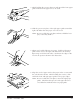
Changing a toner bottle A toner bottle will print approximately 6,000 pages of A4 size paper when the black-to-white ratio on the prints is 12%. When the cartridge is out of toner, the toner empty indicator will light on the operation panel. Replace the toner bottle by following the steps below. NOTE: Do not replace the toner bottle except when the toner empty indicator appears. 1. Open the front cover. 1 2. Pull the toner bottle holder lever to swing the toner bottle out of the printer (1).
4. Check that the triangle marks on the toner bottle and the toner bottle holder face each other as in the illustration. Holding the toner bottle with your left hand, gently pull the toner seal out of the toner bottle. 5. Swing the toner bottle holder back into position. 6. Close the front cover.
Changing the toner collection bottle The used toner full indicator will appear on the operation panel approximately every 100,000 prints when the black-to-white ratio on the prints is 12%. When this indicator appears, follow the steps below to replace the toner collection bottle. 1. Take out the toner collection bottle and cover the mouth with the cap attached on the bottle. 2. Insert the new toner collection bottle into the printer.
Appendix A Specifications General specifications Type ..................... Console-type dry electrophotographic printer Resolution ............ 400 DPI Print method ........ Laser diode, polygon mirror system Laser .................... Maximum power: 1.1 x 10 -3 (W) Wavelength: 785 +10, -15 nm Dimensions .......... Width : 36" (860 mm) x depth : 27" (684 mm) x height : 40" (1,006 mm) Weight ................. 253 lb (115 kg) Print speed ........... – First print A4Y: 8 seconds or less A3T: 8.
Option ................. 20-Bin Sorter with Sorter Interface Unit Top Bin of sorter: 100-sheet capacity Bins 2–20: 50-sheet capacity each Paper feeding ....... Four Universal Cassettes each holding 350 sheets Paper types .......... Standard paper: 60-90g/m2 (16–24 lb) Paper sizes Paper Cassette Size A B A3 297 mm (11.7 in.) 420 mm (16.5 in.) A4* 210 mm (8.27 in.) 297 mm (11.7 in.) A5 148 mm (5.83 in.) 210 mm (8.27 in.) JIS B4 257 mm (10.12 in.) 364 mm (14.3 in.) JIS B5* † 182 mm (7.17 in.
Appendix B Installation considerations Space requirements The figures and illustrations below show the minimum space required for the installation of your printer.
Installed with sorter option Unit: mm (inch) 100 (4) 1093 (43) 100 (4) 553 (21 3/4) 684 (27) 500 (19 3/4) 1006 (39 5/8) 540 (21 1/4) B-2 November 1996 A-62032
Installation environment Select the proper environment for using the printer to obtain the optimum service from your printer. It should NOT be placed in a location: — which is exposed to direct sunlight. — which is in the direct air stream of a cooler, heater, or ventilator. — where the temperature and the humidity are extremely high or low. The room temperature should be 10–35°C (50–95°F) and humidity should be 15–85% RH. — which does not have a stable, level floor. — which could easily get wet.
Ordering information for the Printer 7 and accessories Ordering information for consumables for the Printer 7 Handling of consumables CAT No.
Appendix C Printer 7 error, maintenance, and caution codes Error Codes Code Explanation Action Needed A0 No used toner collecting bottle. Seat the toner bottle properly; install one if necessary. A1 No EP unit. Seat the EP unit properly; install a new one if necessary*; or call service. See page 1-3. A2 No fuser. Seat the fuser correctly; install a new one if necessary*; or call service. See page 1-3. A3 Unacceptable paper at the sorter interface. Use paper specified for this printer.
Error Codes (continued) Code Explanation Action Needed 21 The drum-charge corona has malfunctioned. Turn the printer off and then on again. If the problem persists, call for service. 22 The thermistor has malfunctioned. Turn the printer off and then on again. If the problem persists, call for service. 23 An excessively high temperature has been detected. Turn the printer off and then on again. If the problem persists, call for service. 24 A heater lamp has malfunctioned.
Error Codes (continued) Code Explanation Action Needed 55 Elevator tray 2 malfunctioned. Open paper cassette #2. Check paper position, and close paper cassette. If the problem persists, call for service. 56 Elevator tray 3 malfunctioned. Open paper cassette #3. Check paper position, and close paper cassette. If the problem persists, call for service. 57 Elevator tray 4 malfunctioned. Open paper cassette #4. Check paper position, and close paper cassette. If the problem persists, call for service.
Appendix D Maintenance Before conducting any maintenance procedures, follow these precautions: — Before beginning the maintenance procedures, be sure to turn OFF the power ON/OFF switch and unplug the printer’s power cord. — Do not put any equipment that produces a magnetic field near the printer. — Do not attempt to remove the units other than those described in the manual.
2. Remove the (4) paper guides by lifting them straight up. Clean the outside of housing with a soft cloth. 3. Carefully clean the wires using the cleaning pen contained in the accessories for the machine as in the illustration. 4. Reinstall the four paper guides. Insert the image transfer/paper separator charger onto the guides of the suction unit until the charger is locked by the front edge of the guides. Lift up the vacuum unit release lever (M2) and lock it into the EP unit. Close the front cover.
Cleaning the printer The printer should be cleaned on a regular basis to prevent potential malfunctions. Before cleaning the printer, be sure to turn off the power ON/OFF switch and unplug the power cord from the outlet. External cleaning 1. Wipe the cover and external parts of the printer with a dry, soft cloth. If the cover is extremely dirty, use a cloth that has been dampened slightly in a neutral cleaning solution. Internal cleaning 1.
New equipment warranty— Kodak Imagelink Printer 7 Kodak warrants this equipment to function properly for three months from date of shipment. However, certain requirements may dictate a different warranty period. This warranty covers the purchaser of this equipment as well as anyone else who owns it during the warranty period. Warranty repair coverage If this equipment does not function properly during the warranty period, Kodak will provide on-site repair service during Kodak’s normal working hours.
This limitation of liability will not apply to claims for injury to persons or damage to property caused by the sole negligence or fault of Kodak or by persons under its direction or control. The Kodak Imagelink Printer 7 has a rated machine life of 4.8 million print actuations or 5 years, whichever occurs first. Kodak reserves the right to discontinue service agreements or increase the service agreement price when the life expectancy of the printer is reached.
A Acoustic noise, A-1 Adjustable feet, 1-2 Index Mechanical print counter, 1-3, D-1 “Metric” paper position switch, 2-2 B N C Cassettes (see also paper or universal cassettes) Caution codes, C-3 Circuit breaker, 1-2 Consumables handling, B-4 ordering of, B-4 D Dataplate, 1-2 E Electrophotographic unit (see EP unit) Environment, A-1, B-3 EP unit, (See electrophotographic (EP unit), 1-3 Error codes, C-1–C-2 F Feed roller, 1-3 Fusing roller knob (M1), 1-3 Fusing unit, 1-3 G H I “Inch” paper position switch,
status, 2-1 test print function, 2-1 turning on and off, 2-1 Printer cable interface socket, 1-2 Printer front cover, 1-1 Printer left cover, 1-1 Printer rear cover, 1-2 Printer right cover, 1-2 Printer top cover, 1-1 T Test control, 2-1 Toner bottle, 1-3 changing, 2-9, 2-10 Toner bottle holder, 1-3 Toner collection bottle, 1-1 changing, 2-11 Transport roller knob (M5), 1-3 Transport section release plate (M4), 1-3 Q U Universal cassette (see paper cassette) R Release lever (M2), 1-3 S Safety informatio
Business Imaging Systems EASTMAN KODAK COMPANY Rochester, New York 14650 Kodak and Imagelink are trademarks of Eastman Kodak Company. Printed on recycled paper. A-62032 Part No. 3C4923 11/96 © Eastman Kodak Company, 1996 Printed in U.S.A.