Document Scanner 5500 Document Scanner 7500 User’s Guide A-61070 Part No.
Safety Information for Installation Instructions for the Kodak Digital Science Document Scanner 5500 and 7500 IMPORTANT: Equipment shall be installed by qualified personnel. WARNING: Dangerous voltage. Disconnect the main power before installation.
Safety Information for User/Installation Instructions for the Kodak Digital Science Automatic Document Feeder IMPORTANT: Equipment shall be installed by qualified personnel. WARNING: Dangerous voltage. Disconnect the main power before installation.
1 Introduction This manual supports the Kodak Digital Science Document Scanners 5500 and 7500. The Kodak Digital Science Document Scanner 5000/7000 series scanners are high-speed, high-resolution rotary scanners designed for medium- to high-volume digital capture of business documents. The Document Scanners capture printed characters, handwritten text, and graphics from documents of various sizes and thicknesses in an electronic format for indexing and database storage.
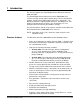
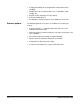
Scanner options 1-2 • Full programmability of all 18 application modes with override capability. • Audible tones for selected functions such as footswitch, patch reading, etc. • English or other language message display. • Convenient table-top size. • An adaptable, modular design for easy addition of accessories. The following optional accessories are available for use with your scanner: • A choice of feeders — automatic document feeder or a semiautomatic document feeder.
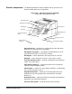
Scanner components The following illustrations and descriptions will help you locate and become familiar with scanner components.
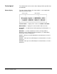
Rear View — Document Scanners 5500/7500 Footswitch connector Coin 1/3 Coin 2 Serial # SCSI connectors Power switch Power cord connector Footswitch connector — allows you to plug in the optional Footswitch accessory. Serial number — provides the serial number and agency approvals. Power switch — toggle this switch to turn the power on (|) or off (O). Power cord connector — plugs into an appropriate power outlet. Coin 1/3 — service/diagnostic interface. Configures the scanner and runs diagnostics.
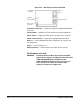
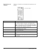
Control panel The control panel consists of the status display and the operation keys and indicators. Status display The status display indicates the image address, current application mode and error messages. Scanner status Mode number Scanner Status — displays if the scanner is enabled or disabled. Mode Number — displays the current mode number or name. Fixed field — an alphanumeric field containing fixed information, i.e., the date. Delimiters — used to separate the levels in an image address.
Operating keys and indicators Following is an illustration and a description of the operating keys and indicators. Two-line status display Key/Indicator Image buffer status Contrast thumbwheel Numeric keys (0-9) Decimal key F key C 1-6 Function Front — green indicates the front side image buffer is available for scanning; red indicates the buffer is not available and the feeder is off (for simplex- and duplex-defined application modes).
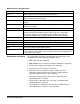
Operating keys and indicators Keys/Indicators Function Next Allows you to enter the next document image address. + Allows you to enter a new value for the image address. When pressed, it allows a field to remain unchanged. Enter Used to enter numeric data for a function code or an image address change. Back Used to move the cursor back one space during numeric data input (the last data input is erased). CAL Starts the calibration process.
2 Getting Started The following steps are necessary to prepare the scanner for operation. Procedures on how to perform these steps are described in this chapter. 1. Turn on the power to the scanner. 2. Select the language display. 3. Calibrate the scanner. 4. Prepare the documents for scanning. 5. Adjust the feed and separator roller gap, if required (semi-automatic feeder). 6. Adjust the feed shelf position. 7. Adjust the feed shelf side guides. 8. Adjust the exit hopper side guides and end stop. 9.
Selecting the language display The scanner may have been configured at installation to allow use of a second language in the status display. The language used (French, German, Italian, Spanish, or other) is defined during installation. If available, the alternate language display may be accessed using function code F19. Calibrating the scanner Calibration sets the intensity of the lamps, which contribute to the overall quality of the scanned document image.
Unsuccessful calibration If calibration is not successful, a message appears in the status display. You may need to: • Verify you are using a clean, blank sheet of paper (at least 12 inches in length) as a calibration target. The paper must be wider than the documents being scanned and at least 8 1/2 inches long. • Verify there is not a document already in the document path. (Refer to the section entitled, “Clearing the document path” in Chapter 7.) • Clean the imaging guides.
Adjusting the feed and separator roller gap (semi-automatic feeder) The gap adjustment knob on the control panel increases or decreases the space between the feed and separator rollers. The gap must be adjusted properly for smooth transportation of documents without document overlap. When documents of different thicknesses are fed in a group, adjust the gap using the thinnest document in the group.
4. Press Run. 5. Select two documents of the same size, texture and thickness, similar to the types of documents you will be scanning. 6. Place one document on top of the other. Hold the documents firmly by their trailing edges. Insert them into the gap approximately 1/8 in. (3 mm). Bottom document separates from top document 7. If the documents separate, repeat the following steps until the documents do not separate: • Turn the gap adjustment knob clockwise 1/2 turn. • Insert the documents again.
12. Press Stop. 13. Enter F04 and disable Counting only. 14. Press Enter. Adjusting the separator roller to scan thick documents To scan thick documents (card or cover stock), use the gap release lever to increase the gap between the feed roller and separator roller. Gap release lever 1. Press down and hold the gap release lever. This opens the gap between the feed and separator rollers and allows thick documents to pass between the rollers. 2.
Adjusting the feed shelf position (semiautomatic feeder only) For manual feeding, the feed shelf can be adjusted in the 0°, 30° or 40° position. For automatic feeding, raise the feed shelf to the 30° or 40° position. 40° position Adjusting the side guides 30° position Before you begin feeding documents into the scanner, adjust the position of the side guides and feed shelf position. • Adjust the width of the feed shelf side guides to hold the widest document you will be scanning.
Adjusting the exit hopper side guides and end stop The exit hopper side guides and end stop must be adjusted so documents are stacked properly. 1. Adjust the exit hopper side guides to hold the widest document you will be scanning. Leave ¼-inch (5 mm) clearance on each side of the document. 2. Adjust the end stop to hold the longest document you will be scanning. An end stop extension is included to accommodate documents up to 17 inches in length.
3. Adjust the height of the exit hopper so the scanned documents naturally fall between the exit hopper side guides and exit hopper end stop.
3 Operating the Scanner Overview This chapter provides instructions for selecting modes, image level settings and feeding documents using the semi-automatic feeder and the automatic feeder. The scanning process consists of the following steps: 1. Prepare the scanner for operation (refer to Chapter 2, Getting Started for more information). 2. Select an application mode for the application. 3. Select the appropriate operating values required for the application on the host computer. 4. Press the Run key. 5.
Setting image levels Image levels are used to identify specific types of documents (or sets of documents) for later indexing and retrieval. The image level assigned to each document is inserted into the image header associated with the document image. There are four document image levels: • • • • Level 0 Level 1 Level 2 Level 3 Setting Levels Levels 1, 2, and 3 can be set by pressing a document Image Level key on the control panel, or by using the optional Footswitch or Patch Reader accessories.
Temporary operating values Each of the 18 modes programmed at the time of installation contain definitions that affect the output of the scanner. Each mode is programmed to conform to the output requirements of a particular application or group of applications. There may be instances, however, when a particular application requires some variation of an existing mode. In such instances, mode definitions may be changed using available function codes.
Feeding documents using the semiautomatic feeder Following are feeder instructions using the semi-automatic feeder. After the scanner has been prepared for operation, the desired mode and any temporary operating values have been defined, you are ready to feed documents into the transport. 4. Verify that the power is on and that all of the proper adjustments have been made (feeder side guides, exit hopper side guides, etc.). 5. Place the feed shelf in the Up position. 6.
7. As you scan documents, set the image level, as required, and periodically remove documents from the exit hopper. NOTE: When the image buffer is full, the feeder will turn off and the image buffer status light will turn red. There may be a momentary pause in scanning while images are being transferred to the host computer. Scanning will resume and the status indicator will change to green when the image buffer is clear. 8.
Feeding thick documents The gap release lever is used to feed thick documents such as card stock or cover stock. The lever is located on the front panel of the scanner next to the gap adjustment knob. (Graphic depicts movement of separator rollers when lever is used) (Graphic depicts gap adjustment) Gap release lever To feed thick documents using the gap release lever: 1.
Feeding documents using the automatic feeder Following are document feeder instructing using the automatic feeder. After the scanner has been prepared for operation, the desired mode and any temporary operating values have been defined, you are ready to feed documents into the transport. 1. Verify that the power is on and that all of the proper adjustments have been made (feeder side guides, exit hopper side guides, etc.). 2. Select a stack of documents that is no more than 1.5 in. (38 mm) thick.
4 Function Codes Using function codes There are a variety of functions available which may be used to temporarily change operating values, and to obtain system and accessory status information. These functions are listed in the Function Code Summary later in this chapter. Following are the procedures for using function codes: 1. Press the F key. 2. Press the numeric keys which correspond to the desired function code. 3. Press Enter.
Function code summary Following is a summary of the functions and their corresponding function code: Application Modes Select Application Mode........................................................ F01 Restore Application Mode ..................................................... F02 Index/Image Address Level 0 .................................................................................. F07 Last Image Address ..............................................................
Bar Code Reader Bar Code Reader ................................................................. F60 Confirmation Tone................................................................. F63 Omit Patch Reading on Next Document................................ F64 Bar Code Test ....................................................................... F65 Document Printers Front and Rear Document Printers ...................................... F40 Front Document Printer ............................................
Function code listing Code F01 Following is a listing of the function codes and descriptions. Function Code Name Select Mode Description Allows you to select one of the predefined application modes. Enter a value from 1 to 18 and press Enter. Allows you to restore the current application mode to its default status, provided mode overrides are not saved. Allows you to count the number of documents entering the scanner without scanning.
Code Function Code Name Description F16 Alarm Tone Allows you to adjust the pitch of the alarm tone. Press the Up arrow to increase the pitch or press the Down arrow to decrease the pitch, then press Enter. F17 Transport System Operation Time Allows you to display the elapsed time of operation of the transport system. This time is recorded in the software and will be reset if a ROM replacement is performed.
Code Function Code Name Description F46 Front Document Printer Vertical Start Print Position Allows you to specify how far from the leading edge of the document printed information will appear. Use the numeric keys to input values between 0.125 and 20 inches (3 to 508 mm) in increments of 0.125 (3mm). The value will correspond to the selected measurement system and should not exceed the document length. The horizontal start print position is changed manually.
Code Function Code Name Description F70 Length Monitor On/Off Allows you to turn the length monitor on or off. The length monitor checks the length of the documents scanned against the predefined minimum/maximum allowable lengths. Messages and/or confirmation tones alert you if the document is shorter or longer than the predefined length. F71 Omit Length Monitor on the Next Document Only Allows you to omit length checking on the next document scanned.
5 Maintenance This chapter provides maintenance procedures for the scanner including cleaning and part replacement procedures.
Daily maintenance procedures Maintenance procedures that should be performed daily include cleaning the imaging guides, feed and separator rollers and the paper path. Cleaning the imaging guides To clean the imaging guides, follow the steps below: IMPORTANT: Do not use any abrasive materials when cleaning the imaging guides. This includes abrasive cleansers, commercial solvents, paper towels, or coarse cloths. 1. Open the side access door. 2.
4. Release and remove the rear imaging guide by swinging the guide toward the front of the scanner (to release it from the two magnets), and lifting it from the scanner’s two mounting pins. 5. Clean the surfaces of both the front and rear imaging guides with an antistatic wiper or a clean, soft, lint-free cloth, slightly moistened with water or lens cleaner. 6. Dry the imaging guides with a dry, lint-free cloth. 7.
9. Swing the vertical transport plate closed and rotate the release handle 180° counterclockwise (so the red arrow aligns with the red rectangle) to latch the plate. Red arrow Red rectangle 10. Close the side access door. 11. Release and lower the horizontal transport plate back into its original position. 12. Lower the release bar and latch the front scan module into its original position. 13. Close the lower access door. 14. Close the upper access door.
Cleaning the feed and separator rollers (semiautomatic feeder) Clean the feed and separator rollers daily to prevent ink, toner, and dust from collecting on the rollers and preventing documents from separating. 1. Lift open the lower access door. CAUTION: Open and close the doors slowly. 2. Lift the release bar to raise the front scan module. 3. Rotate the feed roller cover release lever downward while rotating the feed roller cover to expose the rollers. Do not attempt to remove the assembly.
4. Lift up and latch the horizontal transport plate into its open position. NOTE: If the Patch Reader accessory is installed, it must be removed from the mounting plate in order to lift up the horizontal transport plate. 5. Rotate the feed roller downward and clean with a water-moistened cloth. Continue cleaning until all residue is removed from the roller ribs. 6. Clean the surface of the feed roller assembly with a dry cloth. 7. Clean the separator roller with a dry cloth.
Cleaning the feeder module and separator roller (automatic feeder) Clean the feeder module and separator roller daily to prevent ink, toner, and dust from collecting on the rollers and preventing documents from separating. To clean the feeder module and separator roller: 1. Open the front cover. 2. Push the roller cover release lever toward the back of the machine. 3. Grasp and rotate the roller cover toward the back of the machine, exposing the feeder module and separator roller.
Cleaning the separator roller: 1. Open the front cover. 2. Push the roller cover release lever toward the back of the machine. 3. Grasp and rotate the roller cover toward the back of the machine, exposing the feeder module and separator roller. Roller cover release lever Roller cover Feeder module 4. Lift and remove the separator roller cover plate. 5. Lift the separator roller out of the grooved brackets. Separator roller Grooved brackets 6. Clean the separator roller. 7.
Cleaning the paper path NOTE: Before doing the following procedure, clean the machine thoroughly and use the roller cleaning pads to clean the feed and separator rollers — start with a clean machine. Use the Paper Path Cleaning sheet to clean the paper path rollers. Periodically feed a cleaning sheet with the gum side up through the machine in both the portrait and landscape orientation. Regular use of Paper Path Cleaning sheets may result in fewer major cleanings with the roller cleaning pads.
Weekly maintenance procedures Maintenance procedures that should be performed weekly are vacuuming the inside of the scanner and cleaning the cabinet. Vacuuming inside the scanner Vacuum the inside of the scanner weekly or as required to remove any dust or debris. Vacuuming the horizontal transport area 1. Turn the power off. 2. Lift open the lower access door. CAUTION: Open and close the doors slowly. 3. Lift the release bar to raise the front scan module.
4. Lift up and latch the horizontal transport plate into its open position. NOTE: If the Patch Reader accessory is installed, it must be removed from the mounting plate in order to lift up the horizontal transport plate. 5. Vacuum the lower belt module and transport belts. WARNING: Do not make contact with any electrical components when vacuuming inside the scanner. 6. Release and lower the horizontal transport plate back into its original position. 7.
Vacuuming inside the side access door 1. Turn the power off. 2. Open the side access door. 3. Open the upper access door. 4. Release and open the vertical transport plate by rotating the release handle 180° clockwise. 5. Use a natural bristle cleaning brush to remove debris from inside the transport system.
6. Swing the vertical transport plate closed and rotate the release handle 180° counterclockwise. 7. Vacuum the side access door area. WARNING: Do not make contact with any electrical components when vacuuming inside the scanner. 8. Close the upper access door and side access doors. Cleaning the cabinet A-61070 September 1999 Clean the exterior of the scanner, the feed shelf, and exit hopper with a soft cloth.
Replacement procedures Replacement procedures should be performed on an as-needed basis. Components that need periodic replacement include the exposure lamps and imaging guides. Changing the lamps The exposure system consists of two special, long-life fluorescent lamps. The lamps slide in and out of the scanner for easy lamp replacement: • Always replace both lamps at the same time. If both lamps are not replaced, exposures may not be acceptable. • Use recommended lamps only.
4. Pull the green rear lamp socket holder out from the scanner frame. Be sure to pull the lamp socket holder straight out along its axis. WARNING: Even though you can always handle the green lamp socket holder, the lamp may be very hot. Do not remove the lamp or the lamp socket holder until the lamp has cooled. NOTE: If the lamp socket holder pulls off from the lamp when removing the lamp and socket from the scanner, remove the lamp by grasping the lamp at the end, once it has cooled. 5.
7. Carefully insert the green rear lamp sock holder and rear lamp into the scanner frame. Be sure to insert the lamp socket holder straight in along its axis. 8. Connect the rear lamp cable connector to the scanner electrical system. 9. Repeat Steps 3 through 8, referring to the front lamp, noting that in Step 3 the front lamp cable must be released from the front lamp cable clip, and in Step 6 the clear slit should face towards the rear.
Replacing the imaging guides To replace the imaging guides, follow the steps below: 1. Open the side access door. 2. Release and open the vertical transport plate by rotating the release handle 180° clockwise. 3. Release and remove the front imaging guide by rotating the thumbscrew 90° counterclockwise, and lifting the guide’s two green saddle mounts from the mounting shaft. Magnets Front imaging guide Thumbscrew Rear imaging guide 4.
5. Grasp and hold the new lower imaging guide by the green handle and carefully slide it into place. Make sure the grooves fully engage the track. Rear imaging guide saddle mount Rear imaging guide mounting pin 6. Hold the new front imaging guide by the edges and carefully set it back into the scanner by seating the guide’s two green saddle mounts on to the mounting shaft, and rotating the front imaging guide thumbscrew 90° clockwise. NOTE: The imaging guides are not interchangeable.
7. Swing the vertical transport plate closed and rotate the release handle 180° counterclockwise (so the red arrow aligns with the red rectangle) to latch the plate. Red arrow Red rectangle 8. Close the side access door. 9. Release and lower the horizontal transport plate back into its original position. 10. Lower the release bar and latch the front scan module into its original position. 11. Close the lower access door. 12. Close the upper access door. 13.
Replacing the feeder module and separator roller To replace the feeder module and separator roller, follow the steps below: Replacing the feeder module: 1. Open the front cover. 2. Push the roller cover release lever toward the back of the machine. 3. Grasp and rotate the roller cover toward the back of the machine, exposing the feeder module and separator roller. Roller cover release lever Roller cover Feeder module 4.
Replacing the separator roller: 1. Open the front cover. 2. Push the roller cover release lever toward the back of the machine. 3. Grasp and rotate the roller cover toward the back of the machine, exposing the feeder module and separator roller. Roller cover release lever Roller cover Feeder module 4. Lift and remove the separator roller cover plate. 5. Lift the separator roller out of the grooved brackets. Separator roller Grooved brackets 6.
Ordering replacement parts Ordering cleaning materials 5-22 The following consumable parts can be ordered by calling: 1-800-431-7278. • Imaging guides • − Front: Part No. 986448 − Rear: Part No. 986449 Exposure lamps: 986472 • Automatic Document Feeder Module: CAT No. 123 6066 • Automatic Document Feeder Separator Roller: CAT No. 161 4908 The following cleaning materials can be ordered: • Paper Path Cleaner: Part No. 4C9073 (pack of 50) • Staticide Wipes: Part No.
6 Operator Messages This chapter outlines the actions that should be taken by the user and system administrator when an error message appears in the status display. When a message appears in the status display, you should take the action suggested in the Operator Message Listing. If you cannot solve the problem, call the system administrator. If the problem persists, the system administrator should call Service personnel.
Controlled powerdown sequence Before performing the controlled power-down sequence, determine if the error can be addressed from the host. If so, perform the required host recovery procedures. If the error cannot be addressed from the host, or if the scanner’s error message cannot be cleared when the host recovery procedures are performed, continue with the following power-down sequence. 1. Wait for all information currently held in the buffer to be transferred to the host system. 2.
Operator message listing Code Message Displayed Description/Action Required E101 Auto shut-off Transport will stop and the message will be displayed if a document has not been scanned within one minute. Press Run to continue. Feed documents. E102 Press STOP and try again Tried to use a function code that is not valid while the transport is running. Press Stop and try again. E103 Select valid mode (1 - 18) Invalid application mode was selected. Enter function code F01 to select another mode.
Code E118 E119 Message Displayed Check correct IA/level Description/Action Required Document image level assignment and next image address input conflict. Specify another document image level, or use the Next key to enter a valid image address. E127 Wait image buffr full The image buffer is too full. The feeder will stop feeding documents, but the documents in the transport system will continue to be scanned. Scanning will automatically continue when the image buffer is clear. No action is required.
Code Message Displayed Description/Action Required E139 Confirm tone - not mach enabled Tried to use a confirmation tone function code (F53, F63, F75) but the confirmation tone is not enabled. If a confirmation tone is required, contact your system administrator. E150 Buffer data transfer to host Tried to change function codes via F02. Cannot perform this function while scanned images are in the image buffer. After pressing C, enter F02 again when all images have been read by the host.
Code Message Displayed Description/Action Required E217 Bar Code hardware error At power on, a Bar Code Reader hardware error has been detected. Disable the Bar Code Reader (F60) or select an application mode that does not use the Bar Code Reader. E222 Jam - Feed/Horz Trans Area A document jam has been detected in the feeder or horizontal transport area. • • • E223 Jam - Vert/Trans Exit Area A document jam has been detected in the vertical transport or exit area.
Code E235 Message Displayed Controlled power-down reqrd Description/Action Required This message is displayed along with a more detailed error message. • • • • • Turn the side panel switch off. Turn the main power switch off. Wait 5 to 10 seconds. Turn the main power switch on. Turn the side panel switch on. If the error repeats, call Service. E241 Enter correct IA, re-scan The patch document fed conflicts with the Level key pressed. Verify the current image level and image address.
Code Message Displayed Description/Action Required E261 Fr Cal illumination failure A front lamp failure was detected during calibration. Press Jog to remove the calibration target. Press Cal and try to calibrate the scanner again. If the error persists, verify the optical path is free of obstructions, clean the imaging guides and replace the front and rear (duplex scanners) lamps. E262 Rr Cal illumination failure A rear lamp failure was detected during calibration.
Code Message Displayed Description/Action Required E000 E666 various messages Follow the procedures indicated on the display. If the error persists, turn the scanner off and then on again. If error still persists, call Service. E700 E799 various messages Follow the procedures indicated on the display. If the error persists, turn the scanner off and then on again. If error still persists, call Service. E800 E899 various messages Follow the procedures indicated on the display.
7 Troubleshooting Trouble and remedy chart This chapter outlines some of the problems you may encounter and their probable causes and remedies. Trouble Probable Cause Remedy Scanner does not power on (status display does not illuminate). The power cord is not connected. Push the power cord plug into the receptacle. The wall outlet is defective. Check the outlet (call an authorized electrician.) The power switch is off. Turn the power switch on. The access doors are not closed.
Trouble Probable Cause Remedy Repeated jamming. The transport system plates and operator-accessible areas are not firmly closed. Repeat any recent jam clearing or maintenance procedures, making certain all plates are firmly in place and all operator-accessible areas are closed. Refer to “Clearing the document path” later in this chapter. Documents are skewed during feeding. Adjust guides and feed roller.
Trouble Probable Cause Remedy Some images are not deskewed If you have the Image Manager Accessory installed, and you encounter images that are not deskewed, it may be that the upper left corner could be close enough to the center that when the document is deskewed, part of the document area is cut off. To avoid loss of data, make sure documents are not severely skewed with the left corner in the middle of the scanning width. Repeated low lamp error messages. Lamps may not be properly installed.
Clearing documents Follow the steps below to clear the document path: 1. Check each transport area in turn (Areas A through D) for documents lodged in the document path. You only have to remove the jammed document(s). The Jog feature places the rest of the documents in the exit hopper. Make certain all operator-accessible areas are firmly closed and the transport plates are locked into place. 2. Press and hold down the Jog key to clear any remaining documents. 3.
The feeder area To clear the feeder area (Area A): 1. Turn off the power switch. 2. Lift up the lower access door. CAUTION: Open and close the doors slowly. 3. Raise the front scan module. 4. Rotate the feed roller cover release lever downward while rotating the feed roller cover up to expose the feed roller and separator roller. 5. Press and hold the gap release lever and remove all jammed documents. 6. Rotate the feed roller cover to its original position. 7. Lower and latch the front scan module. 8.
Horizontal transport plate, lower belt module and lower turn areas To clear the horizontal transport plate, lower belt module and lower turn areas (Area B): 1. Turn off the power switch. 2. Lift up the lower access door. CAUTION: Open and close the doors slowly. 3. Raise the front scan module.
4. Lift up and latch the horizontal transport plate into its open position. NOTE: If the Patch Reader accessory is installed, the Patch Reader must be removed from the mounting plate in order to lift up the horizontal transport plate. 5. Remove all jammed documents. 6. Release and lower the transport plate back to its original position. 7. Lower and latch the front scan module. 8. Close the lower access door.
Vertical transport plate and imaging guide areas To clear the vertical transport plate and imaging guide areas (Area B): 1. Turn off the power switch. 2. Open the side access door. 3. Release and swing open the vertical transport plate by rotating the release handle 180° clockwise. 4. Remove all jammed documents.
5. Swing the vertical transport plate closed and rotate the release handle 180° counterclockwise (so the red arrow head aligns with the red rectangle) to latch the plate. NOTE: If the vertical transport plate is not completely closed, documents can lodge in the transport system. Red arrow Red rectangle 6. Close the side access door.
Document exit and upper turn roller areas To clear the document exit and upper turn roller areas (Area D): 1. Turn off the power switch. 2. Lift up and open the upper access door. 3. Remove all jammed documents. CAUTION: Be careful not to damage the antistatic brush when removing the documents. 4. Close the upper access door. Removing non-jammed documents After clearing the document path, follow the steps below to remove any non-jammed documents. 1.
8 Accessories This chapter provides a list of available accessories for the Kodak Digital Science Document Scanner 5500/7500. Operating instructions for most of these accessories can be found in this chapter. Other accessories are available but do not necessarily require any specific operating instructions. Any operating instructions you receive on new accessories can be conveniently placed in this chapter so you can easily access them as needed.
Parts and tools The following parts and tools are needed to properly maintain your system. NOTE: Field Engineers/Specialists are not authorized to order these items; they should be ordered by the customer.
Using the Bar Code Reader The Kodak Digital Science Bar Code Reader 5000/7000 provides a hands-off method of data entry, eliminating the need to manually enter data found on document(s). Bar code image(s) are read, decoded, and converted to a data string of ASCII characters.
Bar code types During installation, the type of bar code used is defined for each mode. The Bar Code Reader is capable of reading and decoding three different types of bar codes. • Code 3 of 9 — also known as Code 39, is a widely used code in which 9 bars or spaces comprise the characters, 3 of which are wide. • Interleaved 2 of 5 — or I 2 of 5, is a compact, interleaved code for numeric characters only. Each digit is represented by 5 bars or spaces, 2 of which are wide.
Bar code placement Bar codes must appear with the bars perpendicular to the leading edge of the document: Leading edge (fed into transport first) Trailing edge In addition, the following must be true: • The bar code must be at least 0.25 in. (6.3 mm) from the leading edge of the document. • The bar code must be at least 0.25 in. (6.3 mm) from the trailing edge of the document. • There must be at least 0.25 in. (6.3 mm) of blank space preceding the start character and following the stop character.
Enabling bar code reading Make sure that Bar Code Reading is enabled before feeding documents. To enable Bar Code Reading at the mode level: • Enter function code F60. If you have enabled the Bar Code Reader, but do not want to read/decode bar code(s) found on the next document only, perform function code F64. Enabling the bar code confirmation tone The bar code confirmation tone may be used to signal that a bar code has been read.
Performing a bar code test Before feeding documents, perform a bar code test (F65) to verify the operation of the Bar Code Reader. NOTE: No document processing, image address changes or level counting, etc. will occur during the test. To perform a bar code test, select one of the test options. 1. Enter function code F65. 2. Select one of the following options.
Function code F65 options may also be used if there is a decline in bar code readability (read rate) during normal document processing. If this occurs, the following steps will assist you in diagnosing the problem: 1. Perform test option 3=Read Rate. This test determines whether or not the reduction in readability is caused by a deficiency in the equipment. − If the resulting read rate is significantly lower than the benchmark given, contact Service.
4. Lift the release bar to raise the front scan module. 5. Lift up and latch the horizontal transport plate into its open position. NOTE: If the Patch Reader accessory is installed, the Patch Reader must be removed from the mounting plate in order to lift up the horizontal transport plate. 6. Open the side access door. Do not leave the side access door open for more than 5 minutes.
7. Release and open the vertical transport plate by rotating the release handle 180° clockwise. Front imaging guide Rear imaging guide Vertical transport plate 8. If the Bar Code Reader is set to read data through the front scan module, remove the front imaging guide. If the Bar Code Reader is set to read data through the rear scan module, remove the rear imaging guide. NOTE: Refer to Chapter 5, Maintenance for procedures on removing the imaging guides.
9. Prepare the bar code to be evaluated by cutting around the bar code so only the vertical black and white bars remain. Cut away all text and surrounding marks or illustrations. NOTE: The bar code used must be the same type indicated in the first line of the status display of the first page. Document and surrounding text 10. Use transparent adhesive tape to adhere the bar code to the appropriate imaging guide in the proper direction.
11. Replace the imaging guide with the bar code attached to it. NOTE: Refer to Chapter 5, Maintenance for procedures on removing the imaging guides. 12. Swing the vertical transport plate closed and rotate the release handle 180° counterclockwise (so the red arrow aligns with the red rectangle) to latch the transport plate. Red arrow Red rectangle 13. Close the side access door. 14. Release and lower the horizontal transport plate back into its original position. 15.
18. Press Enter. Please Wait will be displayed in the status display. BC Type = Please Wait Up to 10 seconds is required for warming the lamps and processing the data. Within 10 seconds, one of the following messages will appear in the status display. Message 1 BC Type = Not Found indicates that the bar code was not read for one of the following reasons: • The type of bar code placed on the imaging guide is not the type indicated in the status display.
Message 3 If the bar code test was successful, the following results will be displayed. Press Enter to access each display. W/N = XX. XX : 1 NEW = .XXXX Press Enter to display the next message: RMIN = XXX% Contrast = .XXX% Press Enter to display the last message: MOD = XXX% DEF = XXX% Grade = X Evaluating test results The results of the Read Rate test will tell you how well your Bar Code Reader is working. The following descriptions and tables will help you determine the results of the bar code test.
Table 1 illustrates how the dimensional field values are converted to a pass/fail status and the print clarity field values are converted to letter grades: Table 1 — Bar Code Grades Grade Field A (Pass) B C D F (Fail) W/N 3:1 to 2:1* 3:1 to 2.2:1** 2:1 to 1:1* 2.2:1 to1:1** NEW 0.080 to 0.010 0.009 to 0.
Table 2 identifies the most common causes of low bar code ratings/grades. Table 2 — Common Causes of Low Bar Code Ratings Field Problem Type Cause W/N NEW Dimensional Bar codes not printed according to specifications (refer to Kodak publication Bar Code Made Easy, A-61099).
Using the Display option The Display option allows you to display the decoded value of an individual bar code as it is fed into the transport. To verify that a bar code is decoded properly: 1. Select 2: DP. BC Type = 1: EV 2: DP 3: Rr 2. Feed a bar code document into the transport. One of the following messages will be displayed: Message 1 BC Type = ? Bar code was not read.
Message 3 BC Type = *XXXXXXXXXXXXX This display gives the decoded value of the bar code read (including the *, representing the start character) is greater than 15. To see the remaining value, press Enter until all characters have been displayed. NOTE: For multiple bar codes on a single document, the asterisk denotes the start of each bar code. However, the asterisk can also be displayed within the data if for some reason a character could not be read. 3.
Using the Read Rate option The Read Rate test option establishes the percentage of bar codes read properly. This option is designed to provide a baseline value as well as the current read rate. A comparison of the two values provides a measure of machine performance over time. When using the Read Rate test option, you can use Kodak Bar Code Standard Test Documents or customer application documents. To use the Read Rate test option: 1. Select 3: Rr. BC Type = 1: EV 2: DP 3: Rr 2.
Using the Footswitch The Kodak Digital Science Footswitch provides a hands-off method of changing document image levels or performing commonly used function(s). You can change a document image level or perform a commonly used function simply by pressing, pressing and holding, or releasing the Footswitch. During installation, modes are defined for use with specific applications.
Footswitch Pressed Definition Footswitch Released actions Sustained Level 0 All documents fed into the transport while the Footswitch is pressed and held are assigned Level 0. Sustained Level 1 All documents fed into the transport while the Footswitch is pressed and held are assigned Level 1. Sustained Level 2 All documents fed into the transport while the Footswitch is pressed and held are assigned Level 2.
Using the Patch Reader The Kodak Digital Science Patch Reader controls document level changes by automatically sensing a pre-defined patch code and changing the document level accordingly. During installation, modes are defined for use with specific applications. Patch reading may be enabled or disabled for each mode. Patch types During installation, the patch type(s) used are defined for each mode. The Patch Reader is capable of reading three types of patches.
Patch code placement Patches may appear parallel to the leading edge of the document: Leading edge (fed into the transport first) In addition: • The top of the patch must be more than 0.20 (5 mm) and less than 0.80 inches (20 mm) from the leading edge of the document. • The bottom of the patch must be no more than 1.6 inches (40 mm) from the leading edge of the document. • There must be at least 0.20 inches (5 mm) of clear space surrounding the patch on all sides.
Patch Reading function codes The following function codes can be enabled (or disabled) when using the Patch Reader accessory. Enabling patch reading — make sure patch reading is enabled before feeding documents. • Patch reading may be enabled or disabled at the mode level using function code F50. Enabling the patch reading confirmation tone — the patch code confirmation tone may be used to signal that a patch has been read.
Changing the horizontal read position The horizontal read position is set by placing the Patch Reader in one of the five reader positions on the mounting plate. NOTE: The five Patch Reader positions are also indicated with a patch mark on the label on the feed tray. The Patch Reader is attached to the mounting plate by magnets. To change the position of the Patch Reader: 1. Lift the Patch Reader off the mounting plate and place it in one of the other four available positions. 2.
Using the Document Printer 5000/7000 The Kodak Digital Science Document Printer 5000/7000 is capable of printing customer-specified information on customer documents. Front and/or rear printers are available. Printed information The information printed by the Document Printer is defined during installation.
Front and rear Document Printer overviews The following illustrations will help you become familiar with the front and rear Document Printer and the mounting plates for the front and rear Document Printer.
Vertical start print position The vertical start print position is defined at installation and determines how far the printed information will appear from the leading edge of the document. Leading edge (fed into transport first) D P 1 T E S T Vertical start print position Trailing edge NOTE: Printing automatically stops ¼-inch (6.3 mm) from the trailing edge of the document, even if the information has not been completely printed.
Horizontal print position The horizontal print position of the front Document Printer is manually set in one of 12 positions on the front Document Printer mounting plate. The horizontal print position of the rear Document Printer is manually set in one of 6 positions on the rear Document Printer mounting plate. The 12 front print positions are indicated with F1 through F12. The 6 rear print positions are indicated with F1 through R6 on the label on the feed tray.
IMPORTANT: When repositioning the front Document Printer, be sure the cable magnet is secured to the front Document Printer mounting plate (not on the Patch Reader mounting plate), so the printer flat cable does not interfere with the optical path between the front imaging guide and the front scan module.
Function codes The following function codes are available if the Document Printer has been installed and the current application mode allows you to use it. F40 allows you to enable/disable both the front and rear Document Printers. F41 allows you to enable/disable the front Document Printer. F42 allows you to enable/disable the rear Document Printer. F44 inhibits printing on the next document entering the feeder. This applies to both the front and rear Document Printers.
Cleaning the ink cartridge Cleaning and priming the ink cartridge will ensure print quality is maintained. IMPORTANT: Ink deposits or spills can occur if you are not careful during the priming procedure. Front Document Printer To check the ink supply in the ink cartridge and/or change the ink cartridge follow the steps below: 1. Turn off the power. 2. Open the lower access door. CAUTION: Open and close the doors slowly. 3. Lift the release bar to raise the front scan module. 4.
5. Lift and remove the front Document Printer carriage from the front Document Printer mounting plate. 6. Raise the holding bar up from the ink cartridge and carriage. 7. Slide the ink cartridge out of the carriage. 8. Examine the ink cartridge for a deflated bladder. If the bladder appears deflated (out of ink), discard the cartridge, obtain a new cartridge and process with Step 10. 9. Check for any accumulation of ink on the jets or face of the ink cartridge.
10. Prime the ink cartridge by carefully inserting the end of a paper clip into the hole at the end of the ink cartridge and gently pushing in on the bladder. Allow a small amount of ink to escape through the jets. Ink cartridge Bladder (inside ink cartridge 11. Remove the paper clip and observe the ink flow back into the bladder through the jets. 12. Use a dry, lint-free cloth to wipe the face and jets of the ink cartridge. 13. Slide the ink cartridge back into the carriage. 14.
8-36 A-61070 September 1999
8. Check for any accumulation of ink on the jets or face of the ink cartridge. Wipe any ink from the jets and face with a clean, dampened lint-free cloth. Jets Ink cartridge face 9. Prime the ink cartridge by carefully inserting the end of a paper clip into the hole at the end of the ink cartridge and gently push in on the bladder. Allow a small amount of ink to escape through the jets. Ink cartridge Bladder (inside ink cartridge 10.
Replacing the ink cartridge Replacing the front Document Printer ink cartridge Replace the ink cartridge when any of the following conditions occur: • The ink bladder appears shrunken or deflated. • The printed characters appear light or uneven. • Missing characters are evident. • The print test function reveals inconsistent character quality. • The cleaning and priming procedure has not improved the overall print quality. To replace the front Document Printer ink cartridge: 1.
5. Lift and remove the front Document Printer carriage from the front Document Printer mounting plate. 6. Raise the holding bar. 7. Slide the ink cartridge out of the carriage. 8. Discard the cartridge and obtain a new cartridge. 9. Slide the ink cartridge into the carriage. 10. Lower the holding bar back down to its original position. 11. If necessary, wipe the carriage clean with a dry, lint-free cloth. 12. Wipe the front Document Printer mounting plate clean of any ink deposits. 13.
Replacing the rear Document Printer ink cartridge To replace the rear Document Printer ink cartridge: 1. Turn off the power. 2. Open the upper access door. 3. Note the current position of the rear Document Printer. 4. Press the carriage spring clips together to remove the rear Document Printer carriage from the rear Document Printer mounting plate. Press spring clips Cable magnet (not shown) 5. Raise the holding bar up from the ink cartridge and carriage. 6. Slide the ink cartridge out of the carriage.
Appendix A Basic Concepts This appendix provides the basic concepts associated with scanning documents. Modes The scanner offers 18 modes that can be defined for a particular application or group of applications. When you select a mode for use with a particular application, you are selecting the format/appearance of the output. Each mode is comprised of definitions that affect the output of the scanner. Required mode definitions include index format, level to follow level rules, etc.
Image addresses An image address is assigned to every document scanned. An image address is composed of four fields, each representing a different document level. An image address has a maximum length of 15 characters; 12 alphanumerics (field A, field B, and field C must be numeric; the fixed field may contain alphanumerics) and 3 delimiters (inserted between fields).
For example, perform the following steps to change the image address from 1201.01.020.005 to 1201.02.000.000. • Press Next or enter function code F97. The cursor will appear over the first fixed field character (1201.01.020.005). • Press + (plus key) to leave the image address field (1201) unchanged. • Enter .02.000.000. • Press Enter to exit, saving the changes to the image address and return to a normal operating display.
For example, perform the following steps to change from 1201 to change it to DEC5: 1. Enter function code F92. The entry cursor appears over the first fixed field character (1201). 2. Press the Up or Down arrow key to enter alpha entry mode. 3. If the letter D is not displayed, press the Up or Down arrow key until it is displayed. 4. Use the Left or Right arrow key to position the flashing cursor over the letter D. 5. Press Enter to place the letter D in the first fixed field character position.
Indexing schemes Documents are scanned to record the information contained on them in an easily accessible form. An indexing scheme is used to access or retrieve the information recorded and is defined during installation for each mode.
Two level indexing When using two level indexing, the image address assigned to each document is defined as follows: • Field A (Level 1) is defined as having a field length greater than 0 • Field B (Level 2) is defined as having a field length greater than 0 • Field C (Level 3) is defined as having a field length of 0 • Fixed field may be defined, if desired For example, if you scan a book with 2 chapters (Chapter 1 has 40 pages and Chapter 2 has 60 pages) the image address has been defined: • • •
Two level offset indexing When using two level offset indexing, the image address assigned to each document is defined as follows: • Field A (Level 1) is defined as having a field length of 0 • Field B (Level 2) is defined as having a field length greater than 0 • Field C (Level 3) is defined as having a field length of 0 • Fixed field may be defined, if desired For example, if you scan a book with 2 chapters (Chapter 1 has 40 pages and Chapter 2 has 60 pages), the image address has been defined: •
Three level indexing When using three level indexing, the image address assigned to each document is defined as follows: • • • • Field A (Level 1) is defined as having a field length greater than 0 Field B (Level 2) is defined as having a field length greater than 0 Field C (Level 3) is defined as having a field length greater than 0 Fixed field may be defined, if desired For example, if you scan a book with two sections (Section 1 contains 2 chapters, each having 40 pages; Section 2 contains only 1 chap
Three level offset indexing When using three level offset indexing, the image address assigned to each document is defined as follows: • • • • Field A (Level 1) is defined as having a field length of 0 Field B (Level 2) is defined as having a field length greater than 0 Field C (Level 3) is defined as having a field length greater than 0 Fixed field may be defined, if desired For example, if you scan a book with two sections (Section 1 contains 2 chapters, each having 40 pages; Section 2 contains only 1
Controlling document level changes The previous Indexing Schemes examples have illustrated how document levels change within a single group of documents. There are four document image levels: 3, 2, 1, and 0. There are a number of ways in which you can set or change the document level: • You may press a document level key on the control panel to assign a document Level 3, 2, or 1. • You may use function code F07 to assign a document Level 0.
Special considerations Checking the meters It is useful to check the meters to determine maintenance schedules and the length of time required to complete a job. To view the run time display, enter function code F17. The display shows three meters: • • • Meter A shows the number of motor-on hours Meter B shows the number of transport-on hours Meter C shows the number of AC-on hours Press C (Clear) to clear the display.
EASTMAN KODAK COMPANY Document Imaging Rochester, New York 14650 Kodak, Digital Science and the ds monogram symbol, and Imagelink are trademarks of Eastman Kodak Company. Printed on recycled paper. A-61070 9/99 © Eastman Kodak Company, 1999 Printed in U.S.A.