DIGITAL SCIENCETM and IMAGELINKTM Scanners Installation Questionnaire Instructions A-61097 Part Number 4C8894 Mode Setup Instructions
1 Introduction The KODAK DIGITAL SCIENCE™ Mode Setup Software 9000 has been developed to enable you to customize applications using the: • • • • • • • KODAK DIGITAL SCIENCE Document Scanner 9500 KODAK DIGITAL SCIENCE Scanner/Microimager 990 KODAK IMAGELINK Microimager 70 KODAK IMAGELINK Microimager 70 with Advanced Function Module KODAK IMAGELINK Scanner 900 KODAK IMAGELINK Scanner 923, or KODAK IMAGELINK Scanner/Microimager 990.
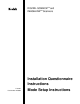
Software Installation Procedure Follow these steps to install the software: 1. Insert the Mode Setup Software diskette into the drive. 2. Type A:INSTALL next to the DOS prompt and press Return/Enter. If the disk drive on your unit is not designated as the A drive, substitute the correct drive designation in this command string.
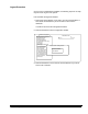
. Enter the desired drive and directory designations and press Enter. Directory Information Drive To Install From: A Drive To Install To: C Directory To Be Installed To: \SETUP ESCAPE to Abort [Press ENTER to Accept, any other key to Edit] 5. Press Enter to continue the logon procedure. Press any other key to alter the drive and directory designations. Mode Setup Software Please Wait While Files Are Being Copied To Your Destination Drive.
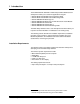
During the installation procedure, the following window will appear if you don’t have the files and buffers set correctly in the config.sys file: Mode Setup Software INSTALLING Please Wait While Files Are Being Copied ToYour Destination Drive. The CONFIG.SYS File Needs To Be Checked To Make Sure That BUFFERS=40 FILES=40 Next, the following windows will appear: Mode Setup Software INSTALLING Please Wait While Files Are Being Copied To Your Destination Drive.
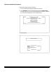
REGISTRATION Please enter the name of the registered user below: ____________________________________ Please Wait While Files Are Being Copied To Your Destination Drive. FILE COPY COMPLETE 7. Type in user name. Press Return/Enter. Type “setup” in c:\setup directory to start Mode Setup 8. Press any key to return to DOS. 9. Eject the Mode Setup Software diskette. 10. Type: cd setup. The SETUP directory is displayed. 11. Type: setup. This starts the program.
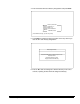
Logon Procedure After the installation procedure has been performed, follow these steps to log on to the Mode Setup Software: 1. Access DOS. 2. Change the directory to correspond to the directory designated during the installation procedure. 3. Type setup and press Return/Enter. * EASTMAN KODAK COMPANY * Model 30 * Model 70/AFM * Model 70 * Model 900 * Model 923 * Model DS990 * Model DS9500 * * * * * This software is the property of Eastman Kodak Company. It is not to be sold or leased in any form.
5. Select Continue.
• Each window should contain an option entitled Previous Menu. Typically, you are returned to the previous menu after completing a definition.
Logout Procedure Once you have completed the installation, the following sequence of steps may be used to log out of the system. From the Mode Configuration window: 1. Select Save & End Session if you wish to save all of the definitions or Don’t Save & End Session if you do not wish to save all of the definitions. You will be returned to the Configuration window. 2. Select End Session from the Configuration window.
2 Machine Definitions The following section lists the items on the Mainframe Configuration Menu that may be selected for definition.
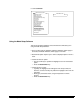
Display Machine Accessories This option displays the status of the various machine accessories and is for viewing only; no selections or entries are made. ■ Microimager 70 ■ Scanner 923 ■ Microimager 70/AFM ■ Scanner/Microimager 990 ■ Scanner 900 ■ Scanner 9500 1. Select Display Machine Accessories. 2. Press Return/Enter to close the Accessory Status window.
Machine ID Number This option establishes a unique identification number for each unit in a multiple-unit installation. The default is 00. ■ Microimager 70 ■ Scanner 923 ■ Microimager 70/AFM ■ Scanner/Microimager 990 ■ Scanner 900 ■ Scanner 9500 1. Select Machine ID Number. 2. Enter a number from 00-99.
Display Language This option defines the primary display language. The default is English. ■ Microimager 70 ■ Scanner 923 ■ Microimager 70/AFM ■ Scanner/Microimager 990 ■ Scanner 900 ■ Scanner 9500 1. Select Display Language. 2. Select the desired language option.
Measurement System This option defines the primary measurement system. English uses inches as the primary unit of measure. Metric uses millimetres as the primary unit of measure. The default is English. ■ Microimager 70 ■ Scanner 923 ■ Microimager 70/AFM ■ Scanner/Microimager 990 ■ Scanner 900 ■ Scanner 9500 1. Select Measurement System. 2. Select the desired unit of measurement.
Programmable Function Keys (P-Keys) This option defines the functions performed by the programmable keys. Refer to Appendix B: Function Codes to determine which function codes and formats to use when programming the P-Keys. ■ Microimager 70 ■ Scanner 923 ■ Microimager 70/AFM ■ Scanner/Microimager 990 ■ Scanner 900 ■ Scanner 9500 1. Select Programmable Function Keys.
The default values are displayed in the Key Definition table. The following values apply only to the Scanner 9500.
The following default values apply only to the Scanner/Microimager 990: Key P1 Definition f04,2 Count only, toggle P2 f45 Print test P3 f09 Total document count P4 f08 Last Image Address P5 f37 Calibrate P6 f30 P7 f44 Amount of film remaining Omit printing on next document only P8 f46 Print position P9 f07 Level 0 P10 f98f38 Stop, End-of-Job To enter a function code, type an f (lower case) followed by a two-digit code (i.e., f04).
Date Format This option defines the date display format, both the date format and delimiter. Refer to Description 1: Date Format Samples for a description of the available formats. The default is mmddyy. The default delimiter is a slash (/). ❏ Microimager 70 ■ Scanner 923 ■ Microimager 70/AFM ■ Scanner/Microimager 990 ■ Scanner 900 ■ Scanner 9500 1. Select Date Format. 2. Select a date format. 3. Select a date delimiter.
Description 1: Date Format Samples Sample Date March 1, 1991 Slash Dash Period Space None mmddyy 03/01/91 03/01/91 03.01.91 03 01 91 030191 mmdd 03/01 03-01 03.01 03 01 0301 ddmmmyy 01/MAR/91 01-MAR-91 01.MAR.91 01 MAR 91 01MAR91 ddmmm 01/MAR 01-MAR 01.MAR 01 MAR 01MAR mmyy 03/91 03-91 03.91 03 91 0391 yddd 1/060 1-060 1.060 1 060 1060 yyddd 91/060 91-060 91.060 91 060 91060 yymmdd 91/03/01 91-03-91 91.03.
Time Format This option defines the time display format. Refer to Description 2: Time Format Samples for a description of the available formats. The default is 12 hour with AM/PM. ❏ Microimager 70 ■ Scanner 923 ■ Microimager 70/AFM ■ Scanner/Microimager 990 ■ Scanner 900 ■ Scanner 9500 1. Select Time Format. 2. Select a specific time format.
Alarm Tone This option defines tone or pitch of the audible alarm. The default is High. ❏ Microimager 70 ■ Scanner 923 ■ Microimager 70/AFM ■ Scanner/Microimager 990 ■ Scanner 900 ■ Scanner 9500 1. Select Alarm Tone. 2. Select the desired alarm tone pitch.
Document Printer/Film Writer Messages This option defines messages that may be printed by a document printer or film writer. ❏ Microimager 70 ■ Scanner 923 ■ Microimager 70/AFM ■ Scanner/Microimager 990 ■ Scanner 900 ■ Scanner 9500 1. Select Doc Printer/Film Writer Msg.
Message 0 is predefined and cannot be changed. Messages 1 through 9 are programmable using the following sequence of steps: 1. Select a message number. 2. Press Return/Enter. 3. Enter the desired message text. 4. Press Return/Enter. Msg 0 Definition Diagnostic Message - No Entry Allowed.
Print Template Setup This option defines as many as ten (10) unique print templates. The template definitions are used when programming Document Printer 12 print definitions. The default print template is Print Template 1, which prints Full IA w/No Delimiters on Line 1. ❏ Microimager 70 ■ Scanner 923 ■ Microimager 70/AFM ■ Scanner/Microimager 990 ■ Scanner 900 ■ Scanner 9500 1. Select DP-12 Print Template. 2. Select a print template (1–10).
1. Follow these steps for each line/item to be printed (maximum twelve per template): a. Select the next available item number (or Item 1 if this is the first item). b. Enter a line number corresponding to the line number on the print template master. c. Select one or more of the print items listed (maximum three items per line). NOTE: Anything over 12 characters will be truncated.
If Check Digit is selected, the following window is displayed: Document Printer 12 Print Template # Item Line Print Item 1 2 3 4 5 6 7 8 9 10 11 12 01 Check Digit Mod 7A - IA Only Mod 11A - IA Only Mod 7B - IA Only Mod 7B - Full IA Mod 10 - IA Only Mod 10 - Full IA Mod 11B - IA Only Mod 11B - Full IA Custom - IA Only Custom - Full IA Previous Menu Previous Menu 3. Select the desired check digit calculation.
The master template is designed to assist you in the placement of information printed by the Document Printer 12. Follow these steps to use the master templates: 1. Obtain a sample of the customer’s document(s). 2. Determine the starting print position (how far from the leading edge of the document printed information should appear). 3. Draw a line on the sample document which corresponds to the starting print position. 4. Copy the master template onto a transparency. 5.
Dotted line = Starting print position (distance from the leading edge of the document). Line 1 Line 2 Line 3 Line 4 Line 5 Line 6 Line 7 Line 8 Line 9 Line 10 Line 11 Line 12 Line 13 Line 14 Line 15 Line 16 Line 17 Line 18 Line 19 Line 20 Line 21 Line 22 Line 23 Line 24 Line 25 Line 26 Line 27 Line 28 Line 29 Line 30 Line 31 Line 32 Line 33 Line 34 Line 35 Line 36 Line 37 Line 38 (5.
Dotted line = Starting print position (distance from the leading edge of the document). Line 1 Line 2 Line 3 Line 4 Line 5 Line 6 Line 7 Line 8 Line 9 Line 10 Line 11 Line 12 Line 13 Line 14 Line 15 Line 16 Line 17 Line 18 Line 19 Line 20 Line 21 Line 22 Line 23 Line 24 Line 25 Line 26 (4 lines per inch) Vertical placement on the document is dependent upon the position of the Document Printer 12 in the transport plate.
Fixed Field Delimiter This option defines the fixed field delimiter used in the Image Address Display. The default is a Period (.). NOTE: The Fixed Field Delimiter doesn’t appear on the display; it appears when printing the Image Address. ❏ Microimager 70 ■ Scanner 923 ■ Microimager 70/AFM ■ Scanner/Microimager 990 ■ Scanner 900 ■ Scanner 9500 1. Select Fixed Field Delimiter. 2. Select the desired Fixed Field delimiter.
Set System Clock This option sets the system clock. ■ Microimager 70 ■ Scanner 923 ■ Microimager 70/AFM ■ Scanner/Microimager 990 ■ Scanner 900 ■ Scanner 9500 1. Select Set System Clock.
3. Verify that the terminal time should be downloaded by selecting Yes; or to cancel the download, select No. If the computer being used to program the unit does not have an internal clock or the internal clock is not accurate: 4. Select the time or date component you wish to define (month, day, year, hour or minute).
Version Numbers This option displays the current software version(s) installed in the machine and is for viewing only; no selections or entries are made. ■ Microimager 70 ■ Scanner 923 ■ Microimager 70/AFM ■ Scanner/Microimager 990 ■ Scanner 900 ■ Scanner 9500 1. Select Version Numbers.
User COIN Port Protocol This option enables or disables the user COIN port for communication protocols associated with OCR data, Document Scanning Array / Bar Code Reader, or Customer specified. The default value is Disabled. ■ Microimager 70 ■ Scanner 923 ■ Microimager 70/AFM ■ Scanner/Microimager 990 ■ Scanner 900 ■ Scanner 9500 1. Select User COIN Port Protocol. 2. Select the desired User COIN Port protocol.
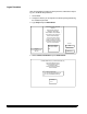
If User-Defined Protocol is selected, the following window will be displayed: Mainframe Configuration Display Machine Accessories Machine ID Number Display Language Measurement System Programmable Function Keys Date Format Time Format Alarm Tone Doc Printer/Film Writer Msg DP-12 Print Template Fixed Field Delimiter Set System Clock Version Numbers User COIN Port Protocol Custom Check Digit OI Hardware Character Set Save Configuration to PC Load Configuration from PC Mode Configuration End Session MACHINE S
5. Select Parity Bit. 6. Select the desired parity.
9. Select Handshaking. 10. Select the handshaking protocol.
Custom Check Digit This option determines the check digit algorithm to be used when a custom check digit is calculated. NOTE: If a standard check digit algorithm is desired, specify the desired algorithm during Image Address print definitions within each mode setup. ❏ Microimager 70 ■ Scanner 923 ■ Microimager 70/AFM ■ Scanner/Microimager 990 ■ Scanner 900 ■ Scanner 9500 1. Select Custom Check Digit.
Custom Check Digit Definition Custom Check Digit Formula Check Digit = Constant 2 - [Sum of IA Digits * Attributes] + Constant 1 Divisor Parameter Attributes Constant 1 Constant 2 Divisor Left/Right LUT Status Lookup Table Current Value 46231546231 00 00 07 Right No abcdefghijk Help Previous Menu The parameters displayed in the Custom Check Digit Definition window must be defined. The following section contains an explanation of each field: • Constant 2—A constant value in the range 0 through 99.
• Constant1—A constant value in the range 0 through 99. • Divisor—a constant value between 0 and 99. NOTE: The divisor is not used if value specified is zero (0). In addition to the parameters in the equation, there are other user defined parameters which affect check digit processing: • Left/Right specifier (also referred to as L/R of Decimal)—Indicates the location of the check digit in relation to the decimal point in the calculation results.
Sample check digit calculation #1 Assume the following: Image Address = 123.45.678.912 Attributes = 46231546231 Constant 1 = 7 Constant 2 = 10 Divisor = 11 Left/Right = Right LUT Status = No/off Lookup Table = abcdefghijk Then the check digit calculation would be: 1. Set up the equation: Check Digit = 10 - [Calculation 1] + 7 Calculation 1 = (2 x 1) + (1 x 3) + (9 x 2) + (8 x 6) + (7 x 4) + (6 x 5) + (5 x 1) + (4 x 3) + (3 x 2) + (2 x 6) + (1 x 4) 2.
Sample check digit calculation #2 Assume the following: Image Address = 123.45.678.912 Attributes = 46231546231 Constant 1 = 7 Constant 2 = 10 Divisor = 11 Left/Right = Right LUT Status = Yes/on Lookup Table = abcdefghijk Then the check digit calculation would be: 1. Set up the equation: Check Digit = 10 - [Calculation 1] + 7 Calculation 1 = (2 x 1) + (1 x 3) + (9 x 2) + (8 x 6) + (7 x 4) + (6 x 5) + (5 x 1) + (4 x 3) + (3 x 2) + (2 x 6) + (1 x 4) 2.
To program a custom check digit algorithm, use the following sequence of steps: 1. Select the Attributes parameter for definition. 2. Enter the desired attribute values. Custom Check Digit Definition Custom Check Digit Formula Check Digit = Constant 2 - [Sum of IA Digits * Attributes] + Constant 1 Divisor Parameter Current Value Attributes Constant 1 Constant 2 Divisor Left/Right LUT Status Lookup Table 46231546231 00 00 07 Right No abcdefghijk Enter attribute values. Req’d entry 11 digits.
5. Select the Constant2 parameter for definition. 6. Enter a value between 00 – 99. Custom Check Digit Definition Custom Check Digit Formula Check Digit = Constant 2 - [Sum of IA Digits * Attributes] + Constant 1 Divisor Parameter Current Value Attributes Constant 1 Constant 2 Divisor Left/Right LUT Status Lookup Table 46231546231 00 00 07 Right No abcdefghijk Enter constant #2. Req’d entry 2 digits. Help 00 Previous Menu To Change: Enter Value To Retain: Press Enter 7.
9. Select the Left/Right parameter for definition. 10. Select the digit to be used during calculation of the check digit. Custom Check Digit Definition Custom Check Digit Formula Check Digit = Constant 2 - [Sum of IA Digits * Attributes] + Constant 1 Divisor Parameter Attributes Constant 1 Constant 2 Divisor Left/Right LUT Status Lookup Table Current Value 46231546231 00 00 07 Right No abcdefghijk Help Start Formula at: Left of Decimal Pt Right of Decimal Pt Previous Menu Previous Menu 11.
13. Select the Lookup Table parameter for definition. 14. Enter the desired lookup table values. Custom Check Digit Definition Custom Check Digit Formula Check Digit = Constant 2 - [Sum of IA Digits * Attributes] + Constant 1 Divisor Parameter Attributes Constant 1 Constant 2 Divisor Left/Right LUT Status Lookup Table Current Value 46231546231 00 00 07 Right No abcdefghijk Enter lookup table. Req’d entry 11 digits.
OI Hardware Character Set This option defines non-English character sets which may be used by the Operator Interface, Document Printers and the Film Writer. English characters are contained in both sets. The default OI character set is Anglo/Japanese. ❏ Microimager 70 ■ Scanner 923 ■ Microimager 70/AFM ■ Scanner/Microimager 990 ■ Scanner 900 ■ Scanner 9500 1. Select OI Hardware Character Set. 2. Enter the desired printer font option. NOTE: The proper hardware display module must be installed.
Save Configuration to PC This option is used to download a configuration file from the scanner or microfilmer onto diskette. This is useful in creating configuration files which may be transported to other units (see the Load Config from PC option). This is also used to create backup files. This option should be performed any time an installation or setup change is completed. ■ Microimager 70 ■ Scanner 923 ■ Microimager 70/AFM ■ Scanner/Microimager 990 ■ Scanner 900 ■ Scanner 9500 1.
Load Configuration from PC This option is used to upload a configuration file from diskette to the scanner or microfilmer. ■ Microimager 70 ■ Scanner 923 ■ Microimager 70/AFM ■ Scanner/Microimager 990 ■ Scanner 900 ■ Scanner 9500 1. Select Load Configuration from PC. 2. Enter a file name to upload.
3 Selecting the Mode Configuration Window This section lists the Mode Definitions for the Scanner/Microimager. Follow these steps to select the Mode Definition screen.
2. Select a mode to be defined. The Mode Configuration window will be displayed, with the Mode Number you selected for definition displayed at the top.
Mode Definitions The following section lists the items on the Mode Configuration Menu that may be selected for definition. Unavailable machine types are indicated by hollow boxes. Mode Name This option defines the mode name. ❏ Microimager 70 ■ Scanner 923 ■ Microimager 70/AFM ■ Scanner/Microimager 990 ■ Scanner 900 ■ Scanner 9500 1. Select Mode Name.
Index Format This mode defines the index format used by the application mode. Refer to Description 3: Index Formats for a description of the index formats. ■ Microimager 70 ■ Scanner 923 ■ Microimager 70/AFM ■ Scanner/Microimager 990 ■ Scanner 900 ■ Scanner 9500 When using a Microimager 70 without the Advanced Function Module installed, only the index format for Mode 8 and Mode 9 may be defined; the index format is predefined and unalterable in Mode 1 through Mode 7.
Description 3: Index Formats There are five Index Format options available: Single Level IA 1 (Level 1) IA 2 (Level 1) IA 3 (Level 1) IA 4 (Level 1) Whenever a small image mark is placed next to a document and/or a document is assigned Level 1, the Image Address field associated with Level 1 (Field A) is incremented. Two Level IA 1.0 (Level 2) IA 1.1 (Level 1) IA 1.2 (Level 1) IA 2.
Description 3: Index Formats (continued) Three Level IA 1.0.0 (Level 3) IA 1.1.0 (Level 2) IA 1.1.1 (Level 1) IA 2.0.0 (Level 3) Whenever a large image mark is placed next to a document and/or a document is assigned Level 3, the Image Address field associated with Level 3 (Field C) is incremented and the fields associated with Level 2 (Field B) and Level 1 (Field A) are set to zero.
Image Address Display Format This mode defines the format of the Image Address display which appears on the control panel. The default is Suppress. ❏ Microimager 70 ■ Scanner 923 ■ Microimager 70/AFM ■ Scanner/Microimager 990 ■ Scanner 900 ■ Scanner 9500 1. Select IA Display Format.
Image Address Field Widths This mode defines the Image Address field widths. Refer to Description 4: Image Address Fields for a description of proper field definitions. ■ Microimager 70 ■ Scanner 923 ■ Microimager 70/AFM ■ Scanner/Microimager 990 ■ Scanner 900 ■ Scanner 9500 When using a Microimager 70 without the Advanced Function Module installed, only the Image Address field widths for Mode 8 and Mode 9 may be defined; the field widths are predefined and unalterable in Mode 1 through Mode 7.
1. Select IA Field Widths.
Description 4: Image Address Fields An Image Address is a unique identifier assigned to each individual document by the Microimager 70, Scanner 900, Scanner 923, Scanner 9500, or Scanner/Microimager 990. An Image Address may contain up to 15 characters, consisting of a maximum of 12 digits Description 4: Image Address Fields. An Image Address is a unique identifier assigned to each individual document by the Microimager 70, Scanner 900, Scanner 923, Scanner 9500, or Scanner/Microimager 990.
Description 4: Image Address Fields (continued) • Two Level Field A is defined as having a field length greater than zero (1 – 9) Field B is defined as having a field length greater than zero (1 – 9) Field C is defined as having a field length of zero (0) Fixed Field may be defined, if desired (0 – 9) • Two Level Offset Field A is defined as having a field length of zero (0) Field B is defined as having a field length greater than zero (1 – 9) Field C is defined as having a field length of zero (0) Fixed Fi
Level Rules This mode defines the level of a document based upon the level of the previous document. These definitions are used as defaults when the document level is not determined by another method (i.e., Footswitch, P-Key, Level Key, etc.
1. Select Level Rules.
Batching This mode defines the number of documents of a specified level to process prior to performing a predefined action. ■ Microimager 70 ■ Scanner 923 ■ Microimager 70/AFM ■ Scanner/Microimager 990 ■ Scanner 900 ■ Scanner 9500 1. Select Batching.
Batch Value Defines the number of documents to be counted prior to performing a predefined action. The default value is 99. ■ Microimager 70 ■ Scanner 923 ■ Microimager 70/AFM ■ Scanner/Microimager 990 ■ Scanner 900 ■ Scanner 9500 1. Select Batch Value.
Start of Batch Function This mode defines the action(s) to be taken prior to processing the document in the batch. The default value is Nothing. ❏ Microimager 70 ■ Scanner 923 ■ Microimager 70/AFM ■ Scanner/Microimager 990 ■ Scanner 900 ■ Scanner 9500 1. Select Start of Batch Function.
End of Batch Function This mode defines the action(s) to be taken after processing the document in the batch. The default value is f98, Stop. ❏ Microimager 70 ■ Scanner 923 ■ Microimager 70/AFM ■ Scanner/Microimager 990 ■ Scanner 900 ■ Scanner 9500 1. Select End of Batch Function.
AEC Mode This mode enables or disables Automatic Exposure Control. Fixed Mode disables Automatic Exposure Control. Auto Mode enables Automatic Exposure Control. The default value is Auto Mode. ■ Microimager 70 ❏ Scanner 923 ■ Microimager 70/AFM ■ Scanner/Microimager 990 ❏ Scanner 900 ❏ Scanner 9500 1. Select AEC Mode.
Film Mode This mode defines the orientation of documents on film. Refer to Description 5: Film Modes for a description of the available film modes. The default value is Duplex. ■ Microimager 70 ❏ Scanner 923 ■ Microimager 70/AFM ■ Scanner/Microimager 990 ❏ Scanner 900 ❏ Scanner 9500 1. Select Film Mode.
• Simplex Mode Simplex format allows one image to be exposed across the film width. A 24:1 reduction ratio is used for this format. • Duplex Mode Duplex format allows front and back images of the same document to be exposed (at the same time) across the film width. A 40:1 or 50:1 reduction ratio is used for this format. • Duo Mode Duo format allows documents to be filmed across one-half of the film width, with additional documents filmed on the adjacent side.
Reduction Ratio This mode defines the level of magnification. The default value is Don’t Care. ❏ Microimager 70 ❏ Scanner 923 ■ Microimager 70/AFM ■ Scanner/Microimager 990 ❏ Scanner 900 ❏ Scanner 9500 1. Select Reduction Ratio.
Number of Cassettes This mode defines the minimum number of cassettes that must be installed during filming. If Two Cassettes is chosen, you must always use two cassettes. If One Cassette is chosen, you may use one or two cassettes. The default value is One Cassette. ■ Microimager 70 ❏ Scanner 923 ■ Microimager 70/AFM ■ Scanner/Microimager 990 ❏ Scanner 900 ❏ Scanner 9500 1. Select # of Cassettes.
Film Writer NOTE: The Film Writing Module must be installed. ■ Microimager 70 ❏ Scanner 923 ■ Microimager 70/AFM ■ Scanner/Microimager 990 ❏ Scanner 900 ❏ Scanner 9500 1. Select Film Writer.
Character Orientation This mode defines the orientation of the information printed by the film writer. The default is Comic. ■ Microimager 70 ❏ Scanner 923 ■ Microimager 70/AFM ■ Scanner/Microimager 990 ❏ Scanner 900 ❏ Scanner 9500 1. Select Character Orientation.
Image Address Print Format This mode defines the format of the Image Address printed on film. The default is Compress. ❏ Microimager 70 ❏ Scanner 923 ■ Microimager 70/AFM ■ Scanner/Microimager 990 ❏ Scanner 900 ❏ Scanner 9500 1. Select Image Addr Print Format.
Write Definitions This mode defines the information printed on film next to each document, based upon the document level. The default value for all levels is . ■ Microimager 70 ❏ Scanner 923 ■ Microimager 70/AFM ■ Scanner/Microimager 990 ❏ Scanner 900 ❏ Scanner 9500 When using a Microimager 70 without the Advanced Function Module installed, a limited number of print items are available.
If different information is to be printed next to documents of different levels: 1. Select Print Sequence – Level # for the desired level.
Image Management Code NOTE: The Film Writing Module must be installed. ■ Microimager 70 ❏ Scanner 923 ■ Microimager 70/AFM ■ Scanner/Microimager 990 ❏ Scanner 900 ❏ Scanner 9500 1. Select Image Mgmt Code.
Status This mode enables or disables the use of IMC options. The default value is Off or Disabled. ■ Microimager 70 ❏ Scanner 923 ■ Microimager 70/AFM ■ Scanner/Microimager 990 ❏ Scanner 900 ❏ Scanner 9500 1. Select Status.
IMT Search Program Number This mode defines the IMT search program number. The default value is 00. ■ Microimager 70 ❏ Scanner 923 ■ Microimager 70/AFM ■ Scanner/Microimager 990 ❏ Scanner 900 ❏ Scanner 9500 1. Select IMT Search Prg Number.
Magnification This mode defines for the KODAK IMAGELINK™ Digital Workstation (with Zoom Lens Accessory) the desired level of magnification. The default value is 20. ■ Microimager 70 ❏ Scanner 923 ■ Microimager 70/AFM ■ Scanner/Microimager 990 ❏ Scanner 900 ❏ Scanner 9500 1. Select Magnification.
Splice Definition This mode defines the desired action when a splice is detected. The default value is Ignore. ■ Microimager 70 ❏ Scanner 923 ■ Microimager 70/AFM ■ Scanner/Microimager 990 ❏ Scanner 900 ❏ Scanner 9500 1. Select Splice Definition.
Image Mark Sizes This mode defines the image mark sizes used (small, medium, and large). The default value is Kodak Standard. ■ Microimager 70 ❏ Scanner 923 ■ Microimager 70/AFM ■ Scanner/Microimager 990 ❏ Scanner 900 ❏ Scanner 9500 1. Select Image Mark Sizes.
Image Polarity This mode defines the polarity of the image marks relative to the polarity of the document images. The default value is Same as Image Mark. ■ Microimager 70 ❏ Scanner 923 ■ Microimager 70/AFM ■ Scanner/Microimager 990 ❏ Scanner 900 ❏ Scanner 9500 1. Select Image Polarity.
Duplex Front Location The mode defines for the KODAK IMAGELINK™ Digital Workstation where the front side image is located. The default value is Same as IM Channel. ■ Microimager 70 ❏ Scanner 923 ■ Microimager 70/AFM ■ Scanner/Microimager 990 ❏ Scanner 900 ❏ Scanner 9500 1. Select Duplex Front Location.
Film Image Orientation The mode defines where the top of the image is located for the KODAK IMAGELINK™ Digital Workstation. The default value is Leading Edge Up. ■ Microimager 70 ❏ Scanner 923 ■ Microimager 70/AFM ■ Scanner/Microimager 990 ❏ Scanner 900 ❏ Scanner 9500 1. Select Film Image Orientation.
Image Offset This mode defines the position of the image marks relative to the leading edge of the document. The default value is 0. ■ Microimager 70 ❏ Scanner 923 ■ Microimager 70/AFM ■ Scanner/Microimager 990 ❏ Scanner 900 ❏ Scanner 9500 1. Select Image Offset.
Length Monitor NOTE: The Advanced Document Controller must be installed. ■ Microimager 70 ■ Scanner 923 ■ Microimager 70/AFM ■ Scanner/Microimager 990 ■ Scanner 900 ■ Scanner 9500 1. Select Length Monitor.
Status This mode enables or disables length monitoring. The default value is Off or Disabled. ■ Microimager 70 ■ Scanner 923 ■ Microimager 70/AFM ■ Scanner/Microimager 990 ■ Scanner 900 ■ Scanner 9500 1. Select Status.
Maximum Document Length This mode defines the maximum document length accepted. The default value is 13.000 inches/325 mm. ■ Microimager 70 ■ Scanner 923 ■ Microimager 70/AFM ■ Scanner/Microimager 990 ■ Scanner 900 ■ Scanner 9500 1. Select Max Document Length.
Minimum Document Length This mode defines the minimum document length accepted. The default value is 02.500 inches/63 mm. ■ Microimager 70 ■ Scanner 923 ■ Microimager 70/AFM ■ Scanner/Microimager 990 ■ Scanner 900 ■ Scanner 9500 1. Select Min Document Length.
Length Error Response This mode defines the action taken if a document is smaller than the minimum length specified or larger than the maximum length specified. The default value is Display and Beep. ■ Microimager 70 ■ Scanner 923 ■ Microimager 70/AFM ■ Scanner/Microimager 990 ■ Scanner 900 ■ Scanner 9500 1. Select Length Err Response.
Skew Monitor ■ Microimager 70 ■ Scanner 923 ■ Microimager 70/AFM ■ Scanner/Microimager 990 ■ Scanner 900 ■ Scanner 9500 NOTE: The Advanced Document Controller must be installed. 1. Select Skew Monitor.
Skew Threshold This mode defines the amount of tolerable skew. If 5 Degrees is selected, an error will be reported if the amount of document skew is between 5 and 30 degrees. If 10 Degrees is selected, an error will be reported if the amount of document skew is between 10 and 30 degrees. Regardless of the option selected, if the amount of document skew is greater than 30 degrees, no error will be reported. The default value is 10 Degrees.
Skew Error Response This mode defines the action taken if the amount of document skew is greater than the threshold specified. The default value is Display and Beep. ■ Microimager 70 ■ Scanner 923 ■ Microimager 70/AFM ■ Scanner/Microimager 990 ■ Scanner 900 ■ Scanner 9500 1. Select Skew Err Response.
Check Stacker NOTE: The Check Stacker must be installed. This mode defines when the check stacker is activated. Continuous will activate the check stacker whenever the side panel switch is on. Documents in Transport will activate the check stacker only when there are documents exiting the transport. The default value is Documents in Transport. ■ Microimager 70 ■ Scanner 923 ■ Microimager 70/AFM ■ Scanner/Microimager 990 ■ Scanner 900 ■ Scanner 9500 1. Select Check Stacker.
Endorser NOTE: The Endorser must be installed. ■ Microimager 70 ■ Scanner 923 ■ Microimager 70/AFM ■ Scanner/Microimager 990 ■ Scanner 900 ■ Scanner 9500 1. Select Endorser.
Endorser Status Enables or disables the endorser. The default value is Off or Disabled. ■ Microimager 70 ■ Scanner 923 ■ Microimager 70/AFM ■ Scanner/Microimager 990 ■ Scanner 900 ■ Scanner 9500 1. Select Status.
Endorser Mode This mode defines whether the endorser will print continually or only once per document. Continuous will activate the Endorser continually. Single Stamp will activate the Endorser only once per document. The default value is Continuous. ■ Microimager 70 ■ Scanner 923 ■ Microimager 70/AFM ■ Scanner/Microimager 990 ■ Scanner 900 ■ Scanner 9500 1. Select Mode.
Endorser Print Position This mode defines how far from the leading edge of the document the endorsement will appear: The default value is 0000.250 inch/ 6.350 mm. ■ Microimager 70 ■ Scanner 923 ■ Microimager 70/AFM ■ Scanner/Microimager 990 ■ Scanner 900 ■ Scanner 9500 1. Select Print Position.
Footswitch Pressed NOTE: The Footswitch accessory must be installed. This mode defines the action which results when the footswitch is pressed. The default is Undefined. ■ Microimager 70 ■ Scanner 923 ■ Microimager 70/AFM ■ Scanner/Microimager 990 ■ Scanner 900 ■ Scanner 9500 When using a Microimager 70 without the Advanced Function Module installed, a limited number of actions are available.
Footswitch Released NOTE: The Footswitch accessory must be installed. This mode defines the action which results when the footswitch is pressed. The default is Undefined. ■ Microimager 70 ■ Scanner 923 ■ Microimager 70/AFM ■ Scanner/Microimager 990 ■ Scanner 900 ■ Scanner 9500 1. Select Ftswitch Pressed.
Footswitch Confirmation Tone NOTE: The Footswitch accessory must be installed. This mode enables or disables the footswitch press confirmation tone. The default is Off or Disabled. ❏ Microimager 70 ■ Scanner 923 ■ Microimager 70/AFM ■ Scanner/Microimager 990 ■ Scanner 900 ■ Scanner 9500 1. Select Ftswitch Cnf Tone.
Patch Reader 1 NOTE: A Patch Reader accessory or Document Scanning Array must be installed. Enables or disables the primary patch reader. The default value is Off or Disabled. ■ Microimager 70 ■ Scanner 923 ■ Microimager 70/AFM ■ Scanner/Microimager 990 ■ Scanner 900 ■ Scanner 9500 1. Select Patch Reader 1.
Patch Reader 2 NOTE: A Patch Reader accessories or Document Scanning Array must be installed. Enables or disables the secondary patch reader. The default value is Off or Disabled. ❏ Microimager 70 ■ Scanner 923 ■ Microimager 70/AFM ❏ Scanner/Microimager 990 ■ Scanner 900 ■ Scanner 9500 1. Select Patch Reader 2.
Patch Definition NOTE: At least one Patch Reader accessory or Document Scanning Array must be installed. ■ Microimager 70 ■ Scanner 923 ■ Microimager 70/AFM ■ Scanner/Microimager 990 ■ Scanner 900 ■ Scanner 9500 1. Select Patch Definition.
Transfer Patch Definition This mode defines which level should be assigned to the next document when a transfer patch is used. The default value is Level 2. ■ Microimager 70 ■ Scanner 923 ■ Microimager 70/AFM ■ Scanner/Microimager 990 ■ Scanner 900 ■ Scanner 9500 1. Select Transfer Patch Definition.
Film Transfer Patches This mode defines whether or not a document containing a transfer patch is to be filmed. The default value is Transfer Patch Filmed. ❏ Microimager 70 ❏ Scanner 923 ■ Microimager 70/AFM ■ Scanner/Microimager 990 ❏ Scanner 900 ❏ Scanner 9500 1. Select Film Transfer Patches.
Patch Recognition This mode defines which patch codes will be recognized by the system. The default value is 2, 3, & T. ❏ Microimager 70 ■ Scanner 923 ■ Microimager 70/AFM ■ Scanner/Microimager 990 ■ Scanner 900 ■ Scanner 9500 1. Select Patch Recognition.
Bar Code NOTE: A Bar Code Reader must be installed. ❏ Microimager 70 ■ Scanner 923 ■ Microimager 70/AFM ■ Scanner/Microimager 990 ■ Scanner 900 ■ Scanner 9500 1. Select Bar Code.
Bar Code Reading Status Enables or disables bar code reading. The default value is Off or Disabled. ❏ Microimager 70 ■ Scanner 923 ■ Microimager 70/AFM ■ Scanner/Microimager 990 ■ Scanner 900 ■ Scanner 9500 1. Select Bar Code Reading Status.
Bar Code Type Identifies the type of bar code which is to be read. The default value is Code 39. ❏ Microimager 70 ■ Scanner 923 ■ Microimager 70/AFM ■ Scanner/Microimager 990 ■ Scanner 900 ■ Scanner 9500 1. Select Bar Code Type.
Number of Bar Code Characters This mode defines the minimum bar code length allowed (in terms of the number of characters encoded). The default value is 3. ❏ Microimager 70 ■ Scanner 923 ■ Microimager 70/AFM ■ Scanner/Microimager 990 ■ Scanner 900 ■ Scanner 9500 1. Select # of Bar Code Characters.
Bar Codes per Document This mode defines the number of bar codes per document to be decoded. The default value is One Code. ❏ Microimager 70 ■ Scanner 923 ■ Microimager 70/AFM ■ Scanner/Microimager 990 ■ Scanner 900 ■ Scanner 9500 1. Select Bar Codes per Document.
Distance Between Codes This mode defines the minimum bar code height allowed. The height of the tallest bar code determines the distance between codes. The default value is 1.000 inch/25.400 mm. ❏ Microimager 70 ■ Scanner 923 ■ Microimager 70/AFM ■ Scanner/Microimager 990 ■ Scanner 900 ■ Scanner 9500 1. Select Distance Between Codes.
Scan Direction This mode defines whether the bar codes may be read in only one direction (from left to right) or in either direction (from left to right or from right to left). The default value is Unidirectional (from left to right only). ❏ Microimager 70 ■ Scanner 923 ■ Microimager 70/AFM ■ Scanner/Microimager 990 ■ Scanner 900 ■ Scanner 9500 1. Select Scan Direction.
Image Processing Enables or disables image processing; indicates whether or not image processing is required to enhance the overall quality of the bar codes used. The default value is Off or Disabled. ❏ Microimager 70 ■ Scanner 923 ■ Microimager 70/AFM ■ Scanner/Microimager 990 ■ Scanner 900 ■ Scanner 9500 1. Select Image Processing.
Partial Read Enabled Enables or disables partial bar code reading. The default value is Off or Disabled. ❏ Microimager 70 ■ Scanner 923 ■ Microimager 70/AFM ■ Scanner/Microimager 990 ■ Scanner 900 ■ Scanner 9500 1. Select Partial Read Enabled.
Minimum Partial Characters NOTE: Partial Reading must be enabled or this definition will be ignored. This mode defines the minimum number of characters which must be properly decoded to constitute a partial read. The default value is 5-80. ❏ Microimager 70 ■ Scanner 923 ■ Microimager 70/AFM ■ Scanner/Microimager 990 ■ Scanner 900 ■ Scanner 9500 1. Select Min. Partial Characters.
DSA Patch Reading Status Enables or disables patch reading using the Document Scanning Array. The default value is Off or Disabled. ❏ Microimager 70 ■ Scanner 923 ■ Microimager 70/AFM ■ Scanner/Microimager 990 ■ Scanner 900 ■ Scanner 9500 1. Select DSA Patch Reading Status.
Patch Horizontal Location This mode defines the position of patches on the document(s) in terms of the distance from the left side of the transport. The default value is 5.12 inches/130.048 mm. ❏ Microimager 70 ■ Scanner 923 ■ Microimager 70/AFM ■ Scanner/Microimager 990 ❏ Scanner 900 ■ Scanner 9500 1. Select Patch Horizontal Location.
End Fed Patch Reading Status Enables or disables end fed patch reading using the Document Scanning Array. The default value is Off or Disabled. ❏ Microimager 70 ■ Scanner 923 ■ Microimager 70/AFM ■ Scanner/Microimager 990 ❏ Scanner 900 ■ Scanner 9500 1. Select End Fed Patch Read Status.
Level Change via Bar Code Enables level changes based upon detection of a bar code. The default value is Undefined. ❏ Microimager 70 ■ Scanner 923 ■ Microimager 70/AFM ■ Scanner/Microimager 990 ❏ Scanner 900 ■ Scanner 9500 1. Select Level Change via Bar Code.
Confirmation Tones NOTE: The tones must have been enabled during machine configuration; otherwise, these definitions will be ignored. ❏ Microimager 70 ■ Scanner 923 ■ Microimager 70/AFM ■ Scanner/Microimager 990 ■ Scanner 900 ■ Scanner 9500 1. Select Confirmation Tone.
Patch Detected Tone NOTE: Patch reading must be enabled. In addition, the confirmation tones must have been enabled during machine definitions; otherwise, this definition will be ignored. This mode enables or disables a confirmation tone issued when a patch document is detected. The default value is Off or Disabled. ❏ Microimager 70 ■ Scanner 923 ■ Microimager 70/AFM ■ Scanner/Microimager 990 ■ Scanner 900 ■ Scanner 9500 1. Select Patch Detected Tone.
Bar Detected Tone NOTE: Bar Code reading must be enabled. In addition, during machine definitions the confirmation tones must have been enabled; otherwise, this definition will be ignored. Enables or disables a confirmation tone issued when a bar code document is detected. The default value is Off or Disabled. ❏ Microimager 70 ■ Scanner 923 ■ Microimager 70/AFM ■ Scanner/Microimager 990 ■ Scanner 900 ■ Scanner 9500 1. Select Bar Detected Tone.
Bar Code/Patch Tone NOTE: Patch reading and Bar Code reading must be enabled. In addition, the confirmation tones must have been enabled during machine definitions; otherwise, this definition will be ignored. Enables or disables a confirmation tone issued when a bar code and a patch are both recognized. The default value is Off or Disabled. ❏ Microimager 70 ■ Scanner 923 ■ Microimager 70/AFM ■ Scanner/Microimager 990 ❏ Scanner 900 ■ Scanner 9500 1. Select Bar Code/Patch Tone.
OCR Status NOTE: The OCR accessory must be installed. Enables or disables Optical Character Recognition. The default value is Off or Disabled. ❏ Microimager 70 ■ Scanner 923 ■ Microimager 70/AFM ■ Scanner/Microimager 990 ■ Scanner 900 ❏ Scanner 9500 1. Select OCR Status.
COIN User Channel NOTE: If the machine definition User COIN Port Protocol was disabled, these definitions will be ignored. Enables or disables the COIN2 user channel. If a standard form of output was chosen during machine definition (Bar Code/KDIS Protocol or OCR Data Protocol), this definition should be set to Enabled which will produce default/standard data output via the COIN2 port.
Transmit Data This mode defines the data output via the COIN2 port when a userdefined protocol (User-Defined KDIS Format or User-Defined Protocol) is chosen during machine definition. The default values are FF/IA for all levels. ❏ Microimager 70 ■ Scanner 923 ■ Microimager 70/AFM ■ Scanner/Microimager 990 ■ Scanner 900 ■ Scanner 9500 If the same information is to be transmitted for documents of all levels: 1. Select Define All Levels.
If different information is to be transmitted for documents of different levels: 1. Select Define Level # for the desired level. Current Transmit Sequence New Transmit Sequence Transmit Items Full Image Address Indexed Field(s) Only Current Field Value Current Day Current Date Current Time Document Counter Roll Number Attachment Count Bar Code Data Nothing Previous Menu When using a Microimager 70 without the Advanced Function Module installed, a limited number of transmit items may be selected.
Printer Control NOTE: The Document Printer Controller must be installed ■ Microimager 70 ■ Scanner 923 ■ Microimager 70/AFM ■ Scanner/Microimager 990 ■ Scanner 900 ■ Scanner 9500 1. Select Printer Control.
Print Position This mode defines how far from the leading edge of the document(s) the information printed by the document printer(s) will appear. The default value is 00.250 inch/6.25 mm. ■ Microimager 70 ■ Scanner 923 ■ Microimager 70/AFM ■ Scanner/Microimager 990 ■ Scanner 900 ■ Scanner 9500 1. Select Print Position.
Special Character Set This mode defines the size font to be printed. Select either the smaller or larger font size when using the Document Printer 12. The default value is Use Smaller Font. NOTE: This selection is not available if the wrong printer driver board is installed. The following message appears: Incorrect revision of 3100 PCB for Bigfoot Font ❏ Microimager 70 ■ Scanner 923 ■ Microimager 70/AFM ■ Scanner/Microimager 990 ■ Scanner 900 ■ Scanner 9500 1. Select Special Character Set.
Primary Document Printer 1 NOTE: A Document Printer 1 accessory must be installed. ■ Microimager 70 ■ Scanner 923 ■ Microimager 70/AFM ■ Scanner/Microimager 990 ■ Scanner 900 ■ Scanner 9500 1. Select Primary DP-1.
Fonts/Orientation This mode defines the size and orientation of the characters printed by the primary Document Printer 1. The default value is Off or Disabled. ■ Microimager 70 ■ Scanner 923 ■ Microimager 70/AFM ■ Scanner/Microimager 990 ■ Scanner 900 ■ Scanner 9500 1. Select Fonts/Orientation.
Print Definitions This mode defines the information printed on each document, based upon the document level. The default values are Nothing Printed for Level 0 documents; Full Image Address with all delimiters for Level 1, Level 2, and Level 3 documents . ■ Microimager 70 ■ Scanner 923 ■ Microimager 70/AFM ■ Scanner/Microimager 990 ■ Scanner 900 ■ Scanner 9500 If the same information is to be printed on documents of all levels: 1. Select Same Format per Level.
If Spaces between items is selected, you must select the desired number of spaces. If Check Digit is selected, the following window is displayed: Check Digit Current Print Sequence Display Values New Print Sequence Display Values Mod 7A Mod 11A Mod 7B Mod 7B Mod 10 Mod 10 Mod 11B Mod 11B Custom Custom IA Only IA Only IA Only Full IA IA Only Full IA IA Only Full IA IA Only Full IA Previous Menu 2. Select the desired check digit calculation.
If different information is to be printed on documents of different levels: 1. Select Print Sequence - Level # for the desired level.
Secondary Document Printer 1 NOTE: Two Document Printer 1 accessories must be installed. ❏ Microimager 70 ■ Scanner 923 ■ Microimager 70/AFM ■ Scanner/Microimager 990 ■ Scanner 900 ■ Scanner 9500 1. Select Secondary DP-1.
Document Printer Status Enables or disables the secondary Document Printer 1. The default value is Off or Disabled. ❏ Microimager 70 ■ Scanner 923 ■ Microimager 70/AFM ■ Scanner/Microimager 990 ■ Scanner 900 ■ Scanner 9500 1. Select Document Printer Status.
Fonts/Orientation—DP2 This mode defines the size and orientation of the characters printed by the secondary Document Printer 1. The default value is Off or Disabled. ❏ Microimager 70 ■ Scanner 923 ■ Microimager 70/AFM ■ Scanner/Microimager 990 ■ Scanner 900 ■ Scanner 9500 1. Select Fonts/Orientation.
Print Definitions—DP2 This mode defines the information printed on each document, based upon the document level. The default values are Nothing Printed for Level 0 documents; Full Image Address with all delimiters for Level 1, Level 2, and Level 3 documents. ❏ Microimager 70 ■ Scanner 923 ■ Microimager 70/AFM ■ Scanner/Microimager 990 ■ Scanner 900 ■ Scanner 9500 If the same information is to be printed on documents of all levels: 1. Select Same Format per Level.
If Check Digit is selected, the following window is displayed: Check Digit Current Print Sequence Display Values New Print Sequence Display Values Mod 7A Mod 11A Mod 7B Mod 7B Mod 10 Mod 10 Mod 11B Mod 11B Custom Custom IA Only IA Only IA Only Full IA IA Only Full IA IA Only Full IA IA Only Full IA Previous Menu 3. Select the desired check digit calculation. If an option which indicates IA Only is chosen, the level fields of the Image Address will be printed; the Fixed Field will not be printed.
If Message Number is selected, the following window is displayed: Current Print Sequence Display Values New Print Sequence Display Values Message Number Message Number 1 Message Number 2 Message Number 3 Message Number 4 Message Number 5 Message Number 6 Message Number 7 Message Number 8 Message Number 9 Previous Menu 4. Select the desired message number. If different information is to be printed on documents of different levels: 5. Select Print Sequence—Level # for the desired level. 6.
Document Printer 12 NOTE: The Document Printer 12 accessory must be installed ■ Microimager 70 ■ Scanner 923 ■ Microimager 70/AFM ■ Scanner/Microimager 990 ■ Scanner 900 ■ Scanner 9500 1. Select Doc. Printer 12.
Document Printer Status—DP12 Enables or disables the Document Printer 12. The default value is Off or Disabled. ■ Microimager 70 ■ Scanner 923 ■ Microimager 70/AFM ■ Scanner/Microimager 990 ■ Scanner 900 ■ Scanner 9500 1. Select Document Printer Status.
Fonts/Orientation—DP12 This mode defines the size and orientation of the characters printed by the Document Printer 12. The default value is Comic Orientation. ■ Microimager 70 ■ Scanner 923 ■ Microimager 70/AFM ■ Scanner/Microimager 990 ■ Scanner 900 ■ Scanner 9500 1. Select Fonts/Orientation.
Print Definitions—DP12 This mode defines the information printed on each document, based upon the document level. The default values are No Print Template for Level 0 documents; Print Template for Level 1, Level 2, and Level 3 documents. The default is IA-No Del. ■ Microimager 70 ■ Scanner 923 ■ Microimager 70/AFM ■ Scanner/Microimager 990 ■ Scanner 900 ■ Scanner 9500 If the same information is to be printed on documents of all levels. 1. Select Same Format per Level.
When using a Microimager 70 with the Advanced Function Module installed, all of the print templates defined during machine configuration are available for selection. 2. Select the print template which contains the information to be printed on all documents. 3. Select Print Sequence—Level # for the desired level.
Document Sorter OFF ❏ Microimager 70 ■ Scanner 923 ■ Microimager 70/AFM ■ Scanner/Microimager 990 ■ Scanner 900 ■ Scanner 9500 Select Document Sorter and the following screen appears: Mode Number: 10 Sort Criteria Default Stopper Level 0 Docs Level 1 Docs Level 2 Docs Level 3 Docs Transfer Patch Level III Patch Level II Patch Bar Code Docs Partial Read BC Docs w/o Bar Code BC/Patch Docs Skewed Documents Length Error Docs Mode Name: Bin MODE10 Document Sorter Status Error Response Sort Criteria Upper D
If 4 selections have been set and you choose a 5th option, the following screen appears: Mode Number: MODE 10 3 Lvl Supprs 4233 2112 None Auto Duplex ????? 1 Roll Comic Off Off Off Xport Off 10 Mode Name: Mode Configuration Mode Name Index Format IA Display Format IA Field Widths Level Rules Batching AEC Mode Film Mode Reduction Ratio # of Cassettes Film Writer Image Mgmt Code Length Monitor Skew Monitor Check Stacker Endorser Not Used Save & End Session Previous Menu MODE10 Ftswitch Pressed Ftswitch R
Film Definition This mode enables or disables filming.
4 Installation Questionnaire General Information CUSTOMER NAME: __________________________________________________________________ CUSTOMER ADDRESS: _______________________________________________________________ __________________________________________________________________________________ CUSTOMER CONTACT: _________________________________PHONE: _______________________ SALES REPRESENTATIVE: ______________________________PHONE: _______________________ TRAINER: __________________________________________
Machine Definitions 0.0 Accessory Status 9.0 Key 0 _____________ Adv. Doc. Controller _____________ Bar Code Reader Messages Definition Diagnostic Message - No entry Allowed. 1 2 _____________ Doc Scanning Array 3 _____________ Check Feeder 4 _____________ Check Stacker 5 _____________ Document Sorter 6 _____________ Endorser 7 8 _____________ Footswitch 9 _____________ Film Writing Module 10.0 _____________ Image Marker _____________ Patch Reader 1 _____________ Patch Reader 2 Doc.
ITEM LINE Print Template # PRINT ITEM ITEM LINE Print Template # PRINT ITEM ITEM LINE 1 1 2 2 2 3 3 3 1 4 4 4 5 5 5 6 6 6 7 7 7 8 8 8 9 9 9 10 10 10 11 11 11 12 12 12 Print Template # ITEM LINE PRINT ITEM _ Print Template # ITEM LINE PRINT ITEM ITEM LINE 1 1 2 2 2 3 3 3 Print Template # PRINT ITEM 1 4 4 4 5 5 5 6 6 6 7 7 7 8 8 8 9 9 9 10 10 10 11 11 11 12 12 12 Print Template # ITEM LINE PRINT ITEM Print Template # PRINT ITEM
Mode Definitions ❑ Original Setup MODE 1 ❑ Update (enter date) __________ 31.1 Length Monitor Filename: _____________.cfg 31.1 _______ Status May be linked with Mode(s): ________________ 31.2 _______ Max. Doc. Length 31.3 _______ Min. Doc. Length __________ 19.0 Mode Name __________ 20.0 Index Format __________ 21.0 Image Address Display Format 22.0 31.4 _______ Error Response 32.0 32.1 _______ Status Image Address Field Widths 32.
Mode Definitions 44.0 MODE 1 COIN User Channel 44.1 Transmit Data 45.0 46.0 ________ Level 0 ________ Level 1 ________ Level 2 ________ Level 3 Printer Control 45.1 _______ IA Print Format 45.2 _______ Print Position 45.3 _______ Special Char Set Primary Document Printer 1 46.1 _______ Status 46.2 _______ Font/Orientation 46.3 Print Definitions 47.0 ________ Level 0 ________ Level 1 ________ Level 2 ________ Level 3 Secondary Document Printer 1 47.1 _______ Status 47.
APPENDIX A : System Map Mainframe Configuration MACHINE STATE Display Machine Accessories Machine ID Number Display Language Measurement System Programmable Function Keys Date Format Time Format Alarm Tone Doc Printer/Film Writer Msg DP-12 Print Template Fixed Field Delimiter Set System Clock Version Numbers User COIN Port Protocol Custom Check Digit OI Hardware Character Set Save to PC Load from PC Mode Configuration End Session Mode Configuration Define Mode 1 Define Mode 2 Define Mode 3 Define Mode 4
Mode Number: 10 Mode Name: Mode to Mode Copy MODE10 Copy From Mode: Copy Mode 1 Copy Mode 2 Copy Mode 3 Copy Mode 4 Copy Mode 5 Copy Mode 6 Copy Mode 7 Copy Mode 8 Copy Mode 9 Copy Mode 10 Copy Mode 11 Copy Mode 12 Copy Mode 13 Copy Mode 14 Copy Mode 15 Copy Mode 16 Copy Mode 17 Copy Mode 18 Copy From Mode: Previous Menu Select Mode to Copy From Mode Number: Copy From Mode: 01 10 Mode Name: Mode to Mode Copy MODE10 Copy From Mode: Copy Mode 1 Copy Mode 2 Copy Mode 3 Copy Mode 4 Copy Mode 5 Copy
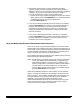
APPENDIX B : Function Codes P-Key Definition Input Code Function Code Name/Description Required F01 Select Mode Allows you to select one of the eighteen (18) application modes. f01 F02 Restore Mode Allows you to restore the current application mode to its default status (as it was defined at installation), provided that mode overrides are not saved. f02 F03* Filming Only Allows you to film documents, with no level counting, endorsing, patch reading, etc.
P-Key Definition Input Code Function Code Name/Description Required F12† Level 2 Count Allows you to display the total number of documents assigned Level 2. Also allows you to reset the count to zero. f12 F13† Level 3 Count Allows you to display the total number of documents assigned Level 3. Also allows you to reset the count to zero. f13 F14 Reset Level Counts Allows you to reset all counters (Level 0, Level 1, Level 2, Level 3, and Total) to zero.
P-Key Definition Input Code Function Code Name/Description Required F26* AEC Fixed Adjust Allows you to adjust the AEC exposure setting when the AEC is in Fixed Mode (OFF). f26 F27†* Film Advance Allows you to advance the film in six (6) inch [150 mm] increments, or by a specific amount input in inches or millimetres. f27 F28†* Film Leader Allows you to create a film leader which is six (6) feet [1.8 metres] of blank film.
P-Key Definition Input Code Function Code Name/Description Required F41 Primary DP1 On/Off Allows you to turn the primary document printer 1 on or off. f41 ,0 ,1 off/disable on/enable F42*** Secondary DP1 On/Off Allows you to turn the secondary document printer 1 on or off. f42 ,0 ,1 off/disable on/enable F43 Document Printer 12 On/Off Allows you to turn the document printer 12 on or off.
P-Key Definition Input Code Function Code Name/Description Required Optional F59 Endorser Print Position Allows you to specify how far from the leading edge of the document the endorsement will appear. f59 F60*** Bar Code Reading 1 On/Off Allows you to turn bar code reading on or off. f60 ,0 ,1 off/disable on/enable F62*** Bar Code/Patch Reading Confirmation Tone Allows you to turn the bar code/patch reading confirmation tone on or off.
P-Key Definition Input Code F76‡ Function Code Name/Description Required Optional OCR On/Off Allows you to turn OCR on or off. f76 ,0 ,1 off/disable on/enable F80 Document Sorter On/Off Allows you to turn the document sorter on or off. f80 ,0 ,1 off/disable on/enable F81† Sort Next Document to Specified Hopper Allows you to specify the hopper (default, upper, or lower) in which the next document only will be deposited.
APPENDIX C : Recommended Entries Item Description Values Item Description Values 0.0 Accessory Status PRES (Present) NOTPRES (Not Present) 14.0 User COIN Port Protocol NO (Not used) YES (Used) 1.0 Machine ID Number 00 – 99 Baud rate 2.0 Display Language ENG (English) FREN (French) GERM (German) ITAL (Italian) SPAN (Spanish) 3.0 Measurement System ENG (English) MET (Metric) 300 600 1200 2400 4800 9600 19.2 K Parity Bit 4.
Item Description Values Item Description Values 22.0 Image Address Field Widths 0–9 30.5 Image Mark Sizes CUST (Custom) KOD (Kodak Standard) 23.0 Level Rules Level 0 Level 1 Level 2 Level 3 30.6 Image Polarity OPP (Opposite of IM) SAME (Same as IM) 30.7 Duplex Front Location OPP (Opposite of channel) SAME (Same as channel) 24.0 Batching 24.1 Level 30.8 None Level 1 Level 2 Level 3 Film Image Orientation DN (Leading Edge down) UP (Leading Edge up) 30.
Item Description Values Item Description Values 36.0 Footswitch Released OFF (Undefined) Level 0 Level 1 Level 2 Level 3 INC (Increment) 41.12 End Fed Patch ON (Enabled) OFF (Disabled) 41.13 Level Change Level 0 Level 1 Level 2 Level 3 OFF (Undefined) 42.0 Confirmation Tones 42.1 Patch Detected 42.2 Bar Code Detected ON (Enabled) OFF (Disabled) 42.3 Bar Code/Patch Detected 43.0 OCR Status ON (Enabled) OFF (Disabled) 44.0 COIN User Channel NO (Not used) YES (Used) Enter data 37.
Item Description Values 47.3 Print Definitions Enter item(s) 48.0 Document Printer 12 48.1 Status ON (Enabled) OFF (Disabled) 48.2 Font/Orientation COM (Comic) COM180 (Comic 180) 48.3 Print Definitions Enter template 49.0 Document Sorter 49.1 Status ON (Enabled) OFF (Disabled) 49.2 Error Response DISP (Display) BEEP (Display and Beep) Stop (Stop and Display) 49.3 Sort Criteria Enter selected criteria and bin 50.0 Mode Overrides DIS (Discard) SAV (Save) 51.
EASTMAN KODAK COMPANY Business Imaging Systems Rochester, New York 14650 Kodak, Digital Science, the ds monogram symbol, and Imagelink are trademarks of Eastman Kodak Company. Printed on recycled paper. A-61097 5/97 © Eastman Kodak Company, 1997 Printed in U.S.A.