Contents 1 Introduction . . . . . . . . . . . . . . . . . . . . . . . . . . . . . . . . . . . . . . . . . . . . . . . . . 1 Scanner features . . . . . . . . . . . . . . . . . . . . . . . . . . . . . . . . . . . . . . . . . . . . . . Supporting documentation . . . . . . . . . . . . . . . . . . . . . . . . . . . . . . . . . . . . . . . Safety information . . . . . . . . . . . . . . . . . . . . . . . . . . . . . . . . . . . . . . . . . . . . . User precautions. . . . . . . . . . . . . . . . . . . . . . . . .
Smart Touch functionality. . . . . . . . . . . . . . . . . . . . . . . . . . . . . . . . . . . . . . . Configuration dialog box . . . . . . . . . . . . . . . . . . . . . . . . . . . . . . . . . . . . . . Scan To settings . . . . . . . . . . . . . . . . . . . . . . . . . . . . . . . . . . . . . . . . . . . . Scan As settings . . . . . . . . . . . . . . . . . . . . . . . . . . . . . . . . . . . . . . . . . . . . Configuring function numbers . . . . . . . . . . . . . . . . . . . . . . . . . . . . . . . . . .
Appendix B Warranty - US and Canada only . . . . . . . . . . . . . . . . . . . . . . . B-1 Limited warranty for Kodak Scanners . . . . . . . . . . . . . . . . . . . . . . . . . . . . .B-1 Warranty exclusions. . . . . . . . . . . . . . . . . . . . . . . . . . . . . . . . . . . . . . . . . . .B-1 Installation Warning and Disclaimer. . . . . . . . . . . . . . . . . . . . . . . . . . . . . . .B-1 How to obtain limited warranty service . . . . . . . . . . . . . . . . . . . . . . . . . . . .
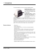
1 Introduction The Kodak i1400 Series Scanners include the following models: Kodak i1410 Scanner — desktop simplex color scanner that scans up to 60 ppm (300 dpi, black and white, landscape orientation) lettersize documents. Kodak i1420 Scanner — desktop duplex color scanner that scans up to 60 ppm (300 dpi, black and white, landscape orientation) lettersize documents.
Supporting documentation In addition to this User’s Guide, the following documentation is also available: • Quick Start Guide — provides a step-by-step procedure for installing the scanner. • Image Processing Guide — explains how to use the basic image processing features. This guide is provided on the installation CD in PDF format and can also be downloaded from the website (www.Kodak.com/go/docimaging).
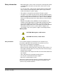
Safety information • When placing the scanner, make sure that the electrical power outlet is located within 1.52 meters (5 feet) of the scanner and is easily accessible. • Use only the power supply that was provided with the Kodak i1400 Series Scanner. Do not substitute another power supply model or another manufacturer’s power supply. • This product is designed for connection to IT power systems.
Environmental information • The Kodak i1400 Series Scanners are designed to meet worldwide environmental requirements. • Guidelines are available for the disposal of consumable items that are replaced during maintenance or service; follow local regulations or contact Kodak locally for more information. • The product packaging is recyclable. • The Kodak i1400 Series Scanners are Energy Star compliant and are shipped from the factory with the default time set to 15 minutes.
Japan This is a Class B product based on the standard of the Voluntary Control Council for interference by information Technology Equipment (VCCI). If this is used near a radio or television receiver in a domestic environment, it may cause radio interference. Install and use the equipment according to the instruction manual. Korean As this equipment has obtained EMC registration for household use, it can be used in any area including residential areas.
2 Getting Started What’s in the box Before you begin open the box and check the contents: • • • • • • • System requirements Kodak i1410, i1420 or i1440 Scanner Input tray Output tray USB 2.
Installing the scanner Install the scanner in the following order: 1. Install the Kodak Driver Software. 2. Connect the power cord to the scanner. 3. Connect the USB cable between your scanner and PC. 4. Attach the input and output trays. 5. Turn the scanner on and finalize the Kodak Driver Software installation. 6. Verify your scanner installation (see Chapter 3) 7. Install other supplied applications (optional). IMPORTANT: Install the Kodak Driver Software on the host PC before you connect the scanner.
The Welcome window will be displayed. 3. Click Next. 4. After reading the agreement, click I Agree. The installation will begin.
5. When the installation is complete, the Installation Completed window will be displayed. 6. Click Finish. Linux operating systems Install the driver software before connecting the scanner to your PC. NOTES: • Depending on the operating system you are installing on (Ubuntu, Fedora, or SUSE) the following procedures may be slightly different. • Kodak Scanner software requires QT3. Verify that your system have these installed (e.g., Fedora: Applications> Add/Remove Software).
Connecting the power cord to the scanner Use only the power supply that was provided with the Kodak i1400 Series Scanner. Do not substitute another power supply model or another manufacturer’s power supply. When the drivers have been installed, connect the power supply and power cord to the scanner. Make sure that the power outlet is located within 1.52 metres (5 feet) of the scanner and is easily accessible. 1.
Connecting the USB cable The USB cable supplied with your scanner has two different ends. A B 1. Attach the B end of the USB cable to the scanner USB port, located on the back of the scanner. 2. Attach the A end of the cable to the proper USB port on your PC. Attaching the input and output trays The input and output trays snap into place. The input and output trays can also be adjusted to fit different document sizes. Attaching the input tray 1. Locate the input tray slots on the scanner. 2.
Attaching the output tray 1. Locate the output tray slots on the scanner and align the output tray pins with the slots. 2. Snap the output tray into place. Turning the scanner on and finalizing Kodak Driver Software installation When the USB cable and power connections have been made, and the Kodak Software Drivers have been installed, the installation will be complete when you turn the scanner on. When the scanner is powered on, it goes through an initialization process.
Scanner components Front view 1 7 2 3 4 A-61550 July 2008 5 6 1 Scanner cover — provides access to the internal components. 2 Output tray — collects the scanned documents. 3 LEDs — illuminates or flashes indicating scanner status. 4 Scanner cover release lever — push up to open the scanner cover. 5 Input tray — holds up to 100 documents (20 lb/75 g/m2) in place. 6 Input tray extender — pull this extender out when scanning documents longer than 21.6 x 27.9 cm (8.5 x 11 inches).
Inside view 1 6 2 5 3 4 1 Separator module — provides smooth document feeding and separation of various sizes, thicknesses and textures of documents. 2 Rollers — provides smooth transport of documents through the scanner. 3 Rear roller cover — provides access to the rear rollers for cleaning. 4 Front roller cover — provides access to the feed module. This cover needs to be removed when cleaning or replacing the feed module or feed module tires.
Side views 3 1 4 2 5 1 Power button — turns the power to the scanner on (|) and off (O). 2 Power port — connects the power cord to the scanner. 3 Side access door — provides access to the upper imaging guide for replacement (The Kodak i1410 Scanner does not have the side access door). 4 USB port — connects the scanner to the PC. 5 Flatbed/USB port — connects the optional A3 Flatbed to the scanner. 6 7 A-61550 July 2008 6 Top LED — flashes red when an error is encountered.
3 Using the Scanner This chapter provides procedures for: • Turning the scanner power on and off • Adjusting the input and output trays • Preparing your documents for scanning • Verifying your scanning installation • Scanning documents: automatic feeding, manual feeding and continuous feeding Turning the scanner on and off • Press the button to the On (I) position. After you turn on the scanner, wait for it to complete the self-test. When completed, the green indicator light will remain on and constant.
Tray extenders and side guides • Both the input and output trays have extenders to accommodate long documents. Grasp the tray extender and pull it out to the desired position. • The output tray has two document stops that can be raised to accommodate the collection of small documents after they have been scanned. • The input tray has side guides that allow you to adjust the feeder to fit different document sizes. Grasp the side guides and slide them in or out to the desired position.
Adjusting the output tray The output tray has three possible positions. Lowest position for long documents Middle position for letter or A4 documents Highest position for checks and small documents • Set the output tray to the lowest position when you are scanning long documents. • Set the output tray to the middle position when you are scanning letter- or A4-size documents.
Start and stop scanning Before you start scanning, make sure the scanner is on and ready for operation, which is indicated by the green indicator light being on and constant. Scanning is controlled by application software designed to capture images. To start and stop scanning, refer to the documentation provided with your application software.
Verifying your scanner installation The following steps help you to verify that your scanner installation was successful. If this procedure is successful, you will be ready to use your scanner. If it is not successful, go back and review the installation procedures outlined in the section entitled, “Installing the scanner” in Chapter 2. Before you begin, be sure the scanner is on and ready to scan. Windows operating systems 1.
5. Click OK. This resets the software to the factory-installed default settings. The factory default settings are set to capture black and white images. For an i1410 Scanner one side of the document will be scanned. For an i1420 or i1440 Scanner both sides of the document will be scanned. The Scan Validation Tool screen will be displayed. 6. Place some test documents into the input tray of the scanner.
Smart Touch functionality Smart Touch functionality allows you to quickly and easily perform common scanning tasks. Predefined tasks are installed with the scanner, however, you can configure Smart Touch to handle the tasks that are most important to you. You can perform any of the tasks by selecting the function from the Smart Touch function listing. Nine different functions can be assigned and performed.
Remove Icon — displays the Remove Icon dialog box. When you click Yes, you will close Smart Touch and remove the Smart Touch icon from the system tray. The software can be started manually by selecting Start>Programs> Kodak>Document Imaging>i1410,i1420,i1440 >Smart Touch. Configuration dialog box The Configuration dialog box allows you to change the tasks associated with each of the 9 function numbers. When you select Configure from the function listing, the Configuration dialog box will be displayed.
Scan To settings Destination — allows you to select one of the following options: • File: creates an electronic file from the scanned documents and saves it in the location specified in the Folder path. • Application: creates an electronic file from the scanned documents and launches the application program for the saved file. For example, if your system is set up to use Adobe Reader to read PDF files, the saved file will be opened using Adobe Reader.
• JPEG/TIFF - Single page: if you are scanning documents with multiple pages or sides, each page or side is saved as a separate JPEG or TIFF file. • TIFF - Multi-page: combines all the scanned images into a single TIFF file. Settings button — if you select PDF - Searchable or RTF as the File Type, the OCR Setup dialog box will be displayed. • Select the language for the searchable PDF or RTF file and click OK.
Scan As settings Setting Shortcut — displays the name of the Setting Shortcut used on the main Kodak Scanner window. This is the shortcut to the collection of scanner settings being used by the scanner. Display settings prior to scanning: if selected, the main Kodak Scanner window will be displayed before the document(s) are scanned, allowing you to select the scanner Setting Shortcut. The main Kodak Scanner window will be displayed each time the function is run.
Configuring function numbers 1. Click the Smart Touch icon on the system tray to display the Smart Touch function listing and select Configure. The Configuration dialog box will be displayed. 2. Select the Task shortcut you want to configure from the Task Shortcut drop-down list. 3. If you want to rename the Task Shortcut, click Rename. The Rename dialog box will be displayed. • Enter the desired name and click OK. 4. Select the desired destination from the Destination drop-down list. 5.
6. By default your documents will be stored within your “My Documents” folder. If you want to change it, enter the folder name or click Browse to select a different folder. 7. If desired, add a file name prefix by entering the text in the File name prefix field. 8. If you want to provide your own file name for the file, select the Name file prior to saving check box on the Configuration dialog box. 9.
Custom destinations Destinations can be added for software applications that are installed on your PC. 1. Click the icon next to the Destination drop-down list to create a new destination. The New dialog box will be displayed. 2. Enter the desired Destination name as you want it to appear in the destination list, then click Browse to select the program. 3. Locate and select the application program (e.g., .exe file) and click Open.
4. The selected program will be added to the New dialog box. 5. Click OK. The new destination is now available in the list. 6. Click Apply to save the new destination. NOTE: The Modify and Delete icons can be used to modify or delete a custom destination. Smart Touch Edit window The Smart Touch Edit window allows you to view the scanned images before sending them to the final destination. As documents are scanned, the images will be displayed in the Edit window.
These icons are available on the Edit window. To use a tool, click on the icon and apply it to the desired image. Start — allows you to scan additional documents and append them to the current images. Stop — cancels the scanning of documents. Magnifier — magnifies a portion of the image. Press and hold the left mouse button inside an image to magnify it. Drag the tool across the image to magnify different areas of the image. Pan — allows you to move the image freely around the window.
Scanning your documents Standard paper size documents should feed easily through the scanner. • Place the documents you want to scan into the input tray of the scanner. If you are scanning one-sided documents or if you have a Kodak i1410 Scanner, be sure the side you want to scan is facing the input tray. Automatic feeding To scan a batch of documents, follow the guidelines for size, type, quantity, etc., as previously described in the “Document preparation” section.
Continuous feeding Continuous feeding allows you to place additional batches of documents in the feeder for “infinite” feeding (with operator assistance). • When only a few documents from one batch remain in the feeder, place the next batch face down on top of those documents. Manual feeding Follow the guidelines for document size, type, weight, quantity, etc. Position the documents face down with the leading edge centered in the automatic document feeder, then start scanning.
4 Document Printing This chapter provides instructions for using the Document Printer and the Enhanced Printer. The following information and procedures can be found in this guide: • Printer specifications. • Changing print positions. • Replacing the ink cartridge and ink blotter strips. NOTE: Refer to the Image Processing document on the CD or your scanning application documentation for more information about enabling printing and setting up print strings.
Printer specifications Characteristic Description Maximum lines 1 Maximum characters 40 Print locations (vertical) Set by capture software application Print orientation 0, 90, 180 or 270 degrees Font size Bold or Normal NOTE: Not all languages can support a Bold font based on the complexity of the characters, such as half-width Katakana. Print side Rear (post-scan) Minimum printing distance from document lead edge 0.89 cm (0.35 in.
Installing/Replacing the ink cartridge Before using the printer, you must install the ink cartridge. After initial installation, replace the ink cartridge when: • • • • printed characters appear light or uneven missing characters are evident a print test reveals inconsistent character quality cleaning has not improved the overall print quality IMPORTANT: Dispose the empty ink cartridge in accordance with all federal, state and local laws. 1. Locate the printer access door on the back of the scanner. 2.
ENHANCED PRINTER 5. If you are installing the ink cartridge for the first time, push the connector on the printer cable firmly into the printer carrier. NOTE: If you are replacing an ink cartridge, the printer cable will already be installed and you just need to remove the printer carrier from it’s position and remove the empty ink cartridge. Push the connector on the printer Remove the printer carrier from it’s cable firmly into the printer carrier. position. 6.
8. Slide the printer carrier into the desired print position. See the section entitled, “Changing print positions” later in the chapter for more information. Print positions 9. Reinstall and close the printer access door. 10. Run a print test.
DOCUMENT PRINTER 5. If you are installing the ink cartridge for the first time, push the connector on the printer cable firmly into the printer carrier. NOTE: If you are replacing an ink cartridge, the printer cable will already be installed and you just need to remove the printer carrier from it’s position and remove the empty ink cartridge. Push the connector on the printer Remove the printer carrier from it’s cable firmly into the printer carrier. position and remove the ink cartridge. 6.
9. Slide the printer carrier into the desired print position. See the section entitled, “Changing print positions” later in this chapter for more information. 10. Reinstall and close the printer access door. 11. Run a print test.
Changing print positions The horizontal print position can be changed manually. Changing the print position 1. Locate the printer access door on the back of the scanner. NOTE: Changing the print position is the same procedure whether you are using the Document Printer or the Enhanced Printer. The photos may be slightly different depending on the printer you are using. 2. Slide your fingers under the printer access door handle and pull the door toward you. 3.
Replacing the ink blotter strips The two ink blotter strips in the scanner transport area collect ink overflow. To order additional ink blotter strips, see the section entitled, “Supplies” later in this guide. 1. Lift up the scanner cover release to unlatch the scanner cover. 2. Pull up to open the scanner cover. 3. Locate the two blotter strip channels. These channels are where the blotter strips will be installed or replaced. Blotter strip channels 4.
7. Align the blotter strip in one of the channels. NOTE: Improperly aligned blotter strips may cause paper jams. 8. Press the adhesive side of the blotter strip down firmly into the channel. 9. Repeat Steps 4-8 for the other strip. 10. Lower the scanner cover and press it firmly until it snaps into place. Supplies A-61550 July 2008 The following supplies are available: Description CAT No.
Problem solving Use the list below as a guide to check possible solutions to problems you may encounter when using the printer. Problem Possible Solution Print quality is poor or inconsistent • • • • Printing problems when starting up due to dry print head Remove the ink cartridge from the scanner and using a damp cloth or swab, dab (do not wipe) the ink jets on the ink cartridge, replace the ink cartridge and try again.
5 Maintenance Cleaning your scanner and preventative maintenance on a regular basis is required to ensure the best possible image quality. Some document types generate more paper dust and debris and may require more frequent cleaning than recommended. NOTES: • Some debris from the rubber tires on the feed and separator modules is normal. Tire debris does not always mean that the tires are worn or damaged.
Supplies and consumables Contact your scanner supplier to order supplies. Supplies/Consumables CAT No.
Cleaning the separator module 1. Power down the scanner. 2. Remove any documents from the feeder area. 3. Lift up the scanner cover release to unlatch the scanner cover. 4. Pull up to open the scanner cover. 5. With one hand, push the separator module release lever back and with the other hand lift the separator module up and out of position.
6. Manually rotate and wipe the separator module tires with a roller cleaning pad. 7. Inspect the tires. If the separator module tires show signs of wear or damage, replace the tires or the separator module. See the section entitled, “Replacing the separator module and separator module tires” later in this chapter for procedures. 8. Insert the separator module and align the shaft ends. 9. Press until the separator module clicks into place.
Cleaning the feed module 1. Push against the raised edge on the left side of the front drive roller cover and pull the cover up and out to remove it. NOTE: You may need to lift the input tray slightly to remove the front roller cover. 2. Remove the feed module by pushing it to the right and lifting it out.
3. Manually rotate and wipe the feed module tires with a roller cleaning pad. 4. Inspect the feed module. If the feed module tires show signs of wear or damage, replace the tires or the feed module. See the section entitled, “Replacing the feed module and feed module tires” later in this chapter for procedures. 5. Remove any dust or debris from the tray area under the feed module and the front roller cover. 6.
Cleaning the drive rollers and transport area 1. Manually rotate and wipe the drive rollers with a roller cleaning pad. 2. Clean any dust or debris in the slots around the drive rollers. 3. Wipe the upper and lower transport areas with a roller cleaning pad. 4. Dry the transport area with a dry Staticide Wipe. 5. Push against the raised edge on the left side of the rear roller cover and pull the cover up and out to remove it. 6. Remove any dust or debris under the rear drive roller cover. 7.
Cleaning the imaging guides Clean the exposed (top side) surfaces of the imaging guides. You do not need to remove the imaging guides for cleaning unless there is dust or dirt on the underside of the imaging guide. If you need to remove the imaging guides, follow the instructions for “Replacing the imaging guides” later in this chapter. 1. Wipe the upper and lower imaging guides with a Staticide Wipe. 2. Dry the imaging guides with a dry Staticide Wipe. 3.
Cleaning the paper path 1. Remove the wrapping from the Transport Cleaning Sheet. 2. Adjust the paper feeder guides to fit the cleaning sheet. 3. Feed the cleaning sheet (adhesive side up) through the scanner in portrait orientation until all residue is removed from the drive rollers. 4. Adjust the feeder guides to fit, then feed the cleaning sheet (adhesive side up) through the scanner in landscape orientation until all residue is removed from the drive rollers. 5.
Replacing the feed module and feed module tires 1. Lift up the scanner cover release to unlatch the scanner cover. 2. Lift up to open the scanner cover. 3. Push against the raised edge on the left side of the front drive roller cover to the side and pull the cover up and out to remove it. NOTE: You may need to lift the input tray slightly to remove the front roller cover. 4. Remove the feed module by pushing it to the right and lifting it out. 5.
6. Lift and remove one core assembly. 7. Remove each tire by sliding it off of the core. 8. Install each new tire by gently stretching it over the core. IMPORTANT: • Do not overstretch the tire; it may tear. • Make sure that the tire is centered on the core and lies flat. 9. Replace the core assembly in the feed module and snap it into place. 10. Repeat Steps 6-9 for the other core assembly. 11. Reinstall the feed module. 12. Reinstall the front roller cover. 13. Close and latch the scanner cover.
Replacing the separator module and separator module tires 1. Lift up the scanner cover release to unlatch the scanner cover. 2. Lift up to open the scanner cover. 3. With one hand, push the separator module release lever back and with the other hand lift the separator module up and out of position. 4. If you are just replacing the separator module, insert the new separator module by aligning the shaft ends and snapping it into position.
NOTE: Use caution as the separation module is spring-loaded and will snap back if you do not hold it in place. 6. Hold onto the separator module in this position with one hand, and with the other hand remove the separator roller. 7. Gently lower the separator module release lever back into place and set the separator module aside. 8. Remove each tire by sliding it off the core. 9. Install each new tire by gently stretching it over the core. IMPORTANT: Do not overstretch the tire; it may tear.
Replacing the preseparation pad 1. Remove the separator module as previously directed. 2. Locate the pre-separation pad on the separator module. 3. Hold the separator module in both hands and find the two preseparation pad side tabs which protrude slightly from the back of the separator module. 4. Push on the pre-separation pad side tabs on the back until the preseparation pad protrudes slightly from the front of the separator module. 5.
Replacing the imaging guides Replacing the upper imaging guide (for i1420 and i1440 Scanners only) 1. Open the scanner cover and locate the door on the right side of the scanner. Removing the side door will allow you to insert a screwdriver through the door opening to access the upper imaging guide. 2. Push down on the tab (shown above), remove the side door and set it aside. 3. Using a Phillips Head screwdriver, loosen the screw from the upper imaging guide bracket (slide the bracket over).
4. Pull gently on the end of the imaging guide and slowly remove it from the scanner. 5. Discard the used imaging guide. 6. Remove any dust or debris from the guide track. Do not allow debris to fall into the scanner. 7. Wipe both sides of the new upper imaging guide with a fresh Staticide Wipe. 8. Dry both sides of the new upper imaging guide with a dry Staticide Wipe. 9. Align the new upper imaging guide in the guide track and slowly push it in. 10.
Replacing the lower imaging guide (for all scanner models) 1. Locate the lower imaging guide. 2. Using a Phillips Head screwdriver, loosen the screw from the lower imaging guide. 3. Slide the imaging guide out of the bracket and remove it from the scanner. 4. Discard the used imaging guide. 5. Remove any dust or debris from the guide track. Do not allow debris to fall into the scanner. 6. Wipe both sides of the new lower imaging guide with a fresh Staticide Wipe. 7.
6 Troubleshooting Occasionally you may encounter a situation with your scanner where it may not function properly. Refer to the information in this chapter to help you resolve the situation before calling Technical Support. Indicator lights and error codes The indicator lights provide information on the current state of the scanner. Red indicator Green indicator Steady green: indicates the scanner is ready to scan. Flashing green: indicates the scanner is scanning or in power saver mode.
Clearing document jams 1. Remove any documents from the feeder area. 2. Lift up the scanner cover release to unlatch the scanner cover. 3. Pull up to open the scanner cover. 4. Locate the jammed document and remove it. 5. Lower the scanner cover and press it down firmly until it latches into place.
Problem solving Use the chart below as a guide to check possible solutions to problems you may encounter when using the Kodak i1400 Series Scanner. Problem The scanner will not scan/ feed documents Possible Solution Make sure that: • the power cord is plugged in and the power is on. • the scanner cover is completely closed. • the proper power-up sequence was followed, the scanner’s green light is on, and the software has enabled scanning. • documents are making contact with the feed module.
Problem Possible Solution Documents are skewed during scanning Make sure that: Scanner pauses excessively during scanning Make sure that: Documents are multifeeding Make sure that: • • • • • • the document side guides are adjusted to fit the documents being fed. documents are being fed perpendicular to the feed module. documents are being fed in the center of the ADF. all staples and paper clips have been removed from the documents. the feed module, separator module, and drive rollers are clean.
Known limitations Linux Issue: The number of pages value is not communicated to the SANE driver. The number of pages is just presented as a “tally” that the XSANE application uses to count the number of images that are captured. Solution: Set the Number of Pages field to a number that is larger than the number of images that will be captured in a batch. Issue: The LED on the scanner is red even though the scanner is securely connected to the PC.
Appendix A Specifications Scanner Type/Speed • i1410 Scanner: simplex color scanner with an automatic document feeder, 60 pages per minute (landscape) • i1420 Scanner: duplex color scanner with an automatic document feeder, 60 pages per minute (landscape) • i1440 Scanner: duplex color scanner with an automatic document feeder, 75 pages per minute (landscape) Scanning Technology CCD type Grayscale output bit depth is: 16 Color capture bit depth is: 16 Color output bit depth is: 8 Output Resolutions 75,
Appendix B Warranty - US and Canada only Congratulations on the purchase of a Kodak Scanner. Kodak Scanners are designed to provide end users with the highest performance and reliability. All Kodak Scanners are covered by the following Limited Warranty.
How to obtain Limited Warranty service Kodak Scanners are supplied with information on unpacking, setup, installation and operation. Careful reading of the User’s Guide will answer most of the technical questions the end user might have regarding proper installation, operation and maintenance of the product. However, should additional technical support be required, you may visit our website at: www.Kodak.
On-site service For the selected Kodak Scanner, and after the Response Center verifies a hardware problem, a service call will be opened and logged. An Kodak Field Engineer will be dispatched to the product location to perform repair service if the product is located within the contiguous forty-eight (48) United States, in certain areas of Alaska and Hawaii, and if there are no security, safety or physical requirements that would restrict the Field Engineer’s access to the scanner.
Contacting Kodak For Information on Kodak Scanners: Website: www.Kodak.com/go/docimaging For U.S. Service, Repair and Technical Assistance by Telephone: Telephone technical support is available Monday-Friday between the hours of 5 a.m. to 5 p.m. excluding Kodak holidays. Phone: (800) 822-1414 For Technical Documentation and FAQ’s available 24 hours a day: Website: www.Kodak.com/go/docimaging For Service Program Information Website: www.Kodak.