i200 Series Scanners User’s Guide A-61167 P/N 3E9296
Contents Introduction . . . . . . . . . . . . . . . . . . . . . . . . . . . . . . . . . . . . . . . . . . . . . . . . . . . . 1 Optional Accessories . . . . . . . . . . . . . . . . . . . . . . . . . . . . . . . . . . . . . . . . . . . 1 Scanner Features . . . . . . . . . . . . . . . . . . . . . . . . . . . . . . . . . . . . . . . . . . . . . . 1 Paper Transport Features . . . . . . . . . . . . . . . . . . . . . . . . . . . . . . . . . . . . . . . 2 Speed/Capacity (Throughput) . . . . . . . . . . . . . . . .
Input and Output Trays . . . . . . . . . . . . . . . . . . . . . . . . . . . . . . . . . . . . . . . . . 15 Attaching the Input Tray . . . . . . . . . . . . . . . . . . . . . . . . . . . . . . . . . . . . . . 15 Attaching the Output Tray . . . . . . . . . . . . . . . . . . . . . . . . . . . . . . . . . . . . 15 Tray Extenders and Side Guides . . . . . . . . . . . . . . . . . . . . . . . . . . . . . . . 15 Adjusting the Output Tray . . . . . . . . . . . . . . . . . . . . . . . . . . . . . . . . . . . .
Appendix A Specifications . . . . . . . . . . . . . . . . . . . . . . . . . . . . . . . . . . . . . A-1 Appendix B Supplies and Accessories . . . . . . . . . . . . . . . . . . . . . . . . . . . B-1 Appendix C KODAK i200 Series Imprinter . . . . . . . . . . . . . . . . . . . . . . . . C-1 Contents of the Imprinter Kit . . . . . . . . . . . . . . . . . . . . . . . . . . . . . . . . . . . . C-1 Installing the Imprinter . . . . . . . . . . . . . . . . . . . . . . . . . . . . . . . . . . . . . . . .
Introduction Before you install and operate your KODAK i200 Series Scanner, take a few minutes to read through this guide. It contains important information about installing, using, and maintaining your scanner. • KODAK i250 Scanner is a desktop simplex color scanner with an automatic document feeder. • KODAK i260 Scanner is a desktop duplex color scanner with an automatic document feeder.
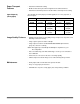
Paper Transport Features • Automatic and manual feeding • Multifeed detection by document length and/or document thickness • Automatic feeder with operator-assisted “infinite” and single-sheet feeding Speed/Capacity (Throughput) The following speeds in pages per minute (ppm) are for color, grayscale, or bitonal output.
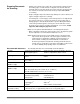
Preparing Documents for Scanning • A batch of documents to be fed into the scanner must be arranged so that the leading edges of all documents are aligned and centered under the automatic paper feeder; this allows the feeder to introduce documents into the scanner one at a time. Documents must be positioned face down for scanning. • Staples and paper clips in documents may damage the scanner. Remove all staples and paper clips before scanning.
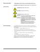
Safety Information • When placing the scanner, make sure that the electrical power outlet is located within 1.52 metres (5 feet) of the scanner and is easily accessible. CAUTION: The power supply must only be used indoors in a dry location. Warning Labels CAUTION: High voltage. Avoid contact. CAUTION: Hot surface. Avoid contact. CAUTION: Moving parts. Avoid contact. WARNING: The scanner front panel must be in place and closed during scanner operation.
Safety and Regulatory Agency Approvals The KODAK i200 Series Scanners conform to all applicable national and international product safety and electronic emission regulatory requirements. This includes, but is not limited to, the following: • Underwriters Laboratories Inc. listing to UL 60950 Third Edition • Underwriters Laboratories Inc. listing to CAN/CSA C22.2 No.
EMC Statements For the United States This equipment has been tested and found to comply with the limits for a Class A digital device pursuant to Part 15 of the FCC rules. These limits are designed to provide reasonable protection against harmful interference when the equipment is operated in a commercial environment.
Installing the Scanner Site Specifications Place the scanner: • in a clean area with temperature and relative humidity typical of an office environment IMPORTANT: Only use the scanner and power supply indoors in a dry location. • on a stable, level work surface capable of supporting the following weights: - i250 Scanner: 12.5 kg (27.5 lb.) - i260 Scanner: 13.9 kg (30.5 lb.) - i250 Scanner with optional flatbed accessory: 19.8 kg (43.5 lb.) - i260 Scanner with optional flatbed accessory: 21.2 kg (46.5 lb.
Unpacking the Scanner The scanner box contains the following items: • KODAK i200 Series Scanner • Input tray • Output tray • Power supply • Power cords (5) for U.S., U.K., Europe, Australia, Asia • Installation CD • Read Me Now sheet • User’s Guide (printed English version; User’s Guide .pdf files in nine other languages are included on the Installation CD) • Registration sheet • Cleaning materials • Calibration target pack NOTE: Save all packing materials for possible future use.
Removing the Foam Sheet The scanner is packed with a foam sheet inside to protect the rollers during shipping. This foam sheet must be removed before you can begin scanning. 1. Lift the scanner out of the box and place it on a stable, level work surface that is capable of supporting it. 2. Lift up the scanner door release to unlatch the scanner door. 3. Pull up to open the scanner door. 4. Remove the foam sheet. 5. Lower the scanner door and press it down firmly until it latches into place.
Rear 1 Imprinter access door (for optional imprinter) 2 Imprinter access door handle 3 IEEE-1394 (FireWire) port 4 Power input 5 Output tray 6 Output tray extender 1 2 3 4 5 6 Side 1 2 3 4 5 Output tray extender Output tray Indicator lights Input tray Input tray extender 3 1 Internal 1 Separator module 2 Drive rollers 3 Channels for ink blotter strips (for optional imprinter) 4 Rear roller cover 5 Front roller cover 6 Feed module 2 4 5 1 2 3 4 5 6 10 A-61167 September 2002
Making Connections Follow the instructions for installing the IEEE-1394 (FireWire) card and the Kodak driver software before you plug the scanner into the host computer. IMPORTANT: You must install the software on the host computer before you install the scanner. Installing the IEEE-1394 (FireWire) Card in the Host Computer An IEEE-1394 six-pin connector is provided on the rear panel of the scanner for IEEE-1394 (FireWire) connectivity. 1.
Power Setup Several power cords are supplied with the scanner. Use only the cord required for your type of power. Dispose of the unneeded power cords properly. Use only the power supply that was provided with the scanner. CAUTION: The power supply must only be used indoors in a dry location. IMPORTANT: Do not substitute another power supply model or another manufacturer’s power supply. 1. Press the side labeled “O” on the power switch to make sure that the power is off.
• If you are installing the scanner on a computer that is running Windows 2000, the following screen appears. Select Yes. Kodak has successfully tested the i200 Series Scanners with Windows 2000. Your scanner is now installed. • If you are installing the scanner on a computer that is running Windows XP, the following screen appears. Select Next. The following screen appears.
Select Continue Anyway. Kodak has successfully tested the i200 Series Scanners with Windows XP. The following screen appears. Select Finish. Your scanner is now installed.
Input and Output Trays The input and output trays snap into place. They also may be adjusted to fit different document sizes. The input and output trays also may be folded flat up against the scanner to save space when the scanner is not in use. Output tray Attaching the Input Tray Document stops Input tray 1. Locate the input tray slots (large holes) on the scanner. 2. Align the input tray pins with the slots. 3. Press the input tray until it snaps into place. Attaching the Output Tray 1.
Adjusting the Output Tray The output tray has three positions. Lowest position for long documents Middle position for letter or A4 documents Highest position for checks • Set the output tray to the lowest position when you are scanning long documents. • Set the output tray to the middle position when you are scanning letteror A4-size documents. • Set the output tray to the highest position with the first document stop when you are scanning checks.
Using the Scanner Starting and Stopping Scanning Scanning is controlled by software developed for your application. To start and stop scanning, refer to the documentation provided with your software. Automatic Feeding To scan a batch of documents, follow the guidelines for size, type, quantity, etc., in the Introduction section. For faster throughput, feed documents into the automatic document feeder (ADF) in landscape orientation (longer side as the leading edge).
Continuous Feeding Continuous feeding allows you to place additional batches of documents in the feeder for “infinite” feeding (with operator assistance). • When only a few documents from one batch remain in the feeder, place the next batch face down on top of those documents. Manual Feeding Follow the guidelines for document size, type, weight, quantity, etc., in the Introduction section. Position the leading edge of the document face down and centered in the ADF, then start scanning.
Maintenance The scanner will collect dust and other debris during routine scanning. Follow the procedures in this section and clean the scanner at least once per week. Clean the scanner and paper path daily if you are scanning carbonless paper or newsprint, or if you are using the imprinter. NOTES: Some debris from the rubber tires on the feed module and separator module is normal. Tire debris does not always mean that the tires are worn or damaged.
5. Remove the separator module by pulling it down and lifting it off. Separator module 6. Manually rotate and wipe the separator module rollers with a roller cleaning pad. 7. Inspect the rollers. If the rollers show signs of wear or damage, replace the separator module. 8. Insert the separator module and align the shaft ends. 9. Press until the separator module clicks into place. 10. Go to the next section to clean the feed module.
Cleaning the Feed Module 1. Push against the raised edge on the left side of the front roller cover to the side and pull the cover up and out to remove it. Front roller cover NOTE: You may need to lift the input tray slightly to remove the front roller cover. 2. Remove the feed module by pushing it to the right and lifting it out. Feed module 3. Manually rotate and wipe the feed module rollers with a roller cleaning pad.
4. Inspect the feed module. If the tires show signs of wear or damage, replace the feed module. 5. Remove any dust or debris from the tray area under the feed module and the front roller cover. 6. Insert the feed module by aligning the pins and pushing it toward the right to fit it into position. 7. Re-install the front roller cover. 8. Go to the next section to clean the drive rollers and transport area. Cleaning the Drive Rollers and Transport Area 1.
5. Push against the raised edge on the left side of the rear roller cover and pull the cover up and out to remove it. Rear roller cover 6. Remove any dust or debris under the rear roller cover. 7. Re-install the rear roller cover. 8. Go to the next section to clean the imaging guides. Cleaning the Imaging Guides 1. Wipe the upper and lower imaging guides with a Staticide Wipe. 2. Dry the imaging guides with a lint-free cloth. 3. Close the scanner door firmly. 4.
Replacing Wear Parts The expected life of customer-replaceable wear parts is shown below. • KODAK Separator Module for i200 Series Scanners: 200,000 document pages • KODAK Feed Module for i200 Series Scanners: 500,000 document pages NOTES: The composition of the roller materials was engineered to provide the ultimate in feeding reliability across the broadest range of document types, sizes, and thicknesses.
Replacing the Feed Module 1. Power down the scanner. 2. Remove any documents from the feeder area. 3. Lift up the scanner door release to unlatch the scanner door. 4. Pull up to open the scanner door. 5. Push against the raised edge on the left side of the front roller cover and pull the cover up and out to remove it. NOTE: You may need to lift the input tray slightly to remove the roller cover. Front roller cover 6. Remove the feed module by pushing it to the right and lifting it out. Feed module 7.
Calibrating the Scanner Calibration optimizes the optical system in your scanner in order to achieve the best overall quality of scanned images. Frequent calibration is not needed or recommended. NOTE: The screens shown in this section are for the TWAIN driver. Your screens may be different. 1. Allow the lamps to warm up for three minutes. 2. Click on Calibrate in the Imaging tab. The Image Chain Calibration dialog box appears. 3. Click Calibrate. A message appears. 4.
Troubleshooting Indicator Lights There are two indicator lights on the scanner. Red indicator light Green indicator light Green on—ready to scan Green flashing—scanner is busy Red on—error mode Red and green on—scanner is powering up After you power up the scanner, the red and green indicator lights will illuminate. After approximately one minute, both lights go out. When the green indicator light comes back on, the scanner is ready to begin scanning.
Adjusting the Separator Module Tension Most documents will feed perfectly fine with the default separator module tension. However, there may be times when you are scanning documents that are lighter or heavier. Two additional positions for the separator module spring allow you to adjust the tension to improve the scanning these types of documents. The spring can be placed in one of the two channels or it can be released and left on the flat surface.
System Is Not Responding If the scanner and/or host computer are not responding, perform the following steps. 1. Power down the computer. 2. Power down the scanner. 3. Disconnect the IEEE-1394 (FireWire) cable from the IEEE-1394 port on the back of the scanner. 4. Power up the computer. 5. Power up the scanner. After you power up the scanner, the red and green indicator lights will illuminate. After approximately one minute, both lights go out.
Problem Solving Occasionally, you may experience a problem with your scanner. In many cases, you can easily fix the problem yourself. To perform suggested maintenance, refer to the Maintenance section. You may also need to check your scanning application. Problem Possible Solution The scanner will not scan/ feed documents Make sure that: Image quality is poor or has decreased Make sure that: Calibration has failed Make sure that: • the power cord is plugged in and the power is on.
Problem Possible Solution Documents are skewed during scanning Make sure that: Scanner pauses excessively during scanning Make sure that: Documents are multifeeding • • • • • the document side guides are adjusted to fit the documents being fed. documents are being fed perpendicular to the feed module. documents are being fed in the center of the ADF. all staples and paper clips have been removed from the documents. the feed module, separator module, and drive rollers are clean.
Appendix A Specifications Scanner Type i250 Scanner: simplex color scanner with automatic document feeder i260 Scanner: duplex color scanner with automatic document feeder Image Capture Resolution 75 dpi to 300 dpi color and bitonal ADF Scanning Speed 50 ppm: 200 dpi landscape A4 42 ppm: 200 dpi portrait letter Scanning Output Bitonal, 256-level, 8-bit grayscale, 24-bit color Output Resolution 75 to 600 dpi File Format Output Color: compressed JPEG, uncompressed TIFF Grayscale: compressed J
Dockable Flatbed Dimensions Height: 16.3 cm (6.4 in.) Width: 48.6 cm (19.1 in.) Length: 64.3 cm (25.3 in.) Dockable Flatbed Weight 7.3 kg (16.0 lb.
Appendix B Supplies and Accessories Contact your scanner supplier to order supplies or visit us online at http://www.kodak.com/go/shop. Item A-61167 September 2002 Catalog No.
Appendix C KODAK i200 Series Imprinter The KODAK i200 Series Imprinter adds imprinting capability to your KODAK i200 Series Scanner. The imprinter prints a date, time, fixed string, and/or sequential number on document backs. Purchase the imprinter separately (Catalog No. 892-7964). The imprinter operates at full scanner speed, and prints on the document after scanning on the rear side of the document (top side as placed in the input tray). Imprinting is controlled through software.
Installing the Imprinter Removing the Circuit Board Cover 1. Make sure that the scanner is powered down and there are no documents in the feeder area. 2. Disconnect the power cord from the back of the scanner. 3. Disconnect the IEEE-1394 (FireWire) cable from the IEEE-1394 port on the back of the scanner. 4. Lift up the scanner door release to unlatch the scanner door. 5. Pull up to open the scanner door. 6. Remove the output tray. 7.
9. Lift up the circuit board cover and remove it. 10. Go to the next section to attach the imprinter board and cable. Attaching the Imprinter Board and Cable The imprinter board is first attached to a mounting bracket which is connected to the main control board, then the imprinter cable is plugged in. IMPORTANT: Use proper precautions to avoid static when you install the imprinter card. 1. Place the imprinter board on the circuit board mounting bracket.
2. Align the three thumbscrews on the imprinter board with the corresponding holes on the circuit board mounting bracket. 3. Loosely attach the imprinter board to the circuit board mounting bracket with the three thumbscrews. 4. Slide the hook near the bottom of the circuit board mounting bracket into the support slot on the main control board. Support slot 5. Press the imprinter board firmly into the main control board.
6. Attach and tighten the fourth thumbscrew on top of the circuit board mounting bracket. 7. Make sure that the imprinter board is seated and secure. 8. Tighten the three thumbscrews that connect the imprinter board and the circuit board mounting bracket. 9. Replace the circuit board cover. 10. Secure the circuit board cover with its two screws. 11. Locate the imprinter connector on the circuit board cover. The imprinter connector should be protruding from the opening on top of the circuit board cover.
12. Attach the end of the imprinter cable that has the metal block (ferrite block end) to the connector in the opening on the circuit board cover. 13. Peel off the backing from the first self-stick hook-and-loop pad that is attached to the imprinter cable. 14. Align the imprinter cable along the channel in the circuit board cover and press the first self-stick hook-and-loop pad firmly to attach it to the circuit board cover. 15.
16. Peel off the backing from the second self-stick hook-and-loop pad that is attached to the imprinter cable. 17. Press the second self-stick hook-and-loop pad firmly to attach it to the circuit board cover. 18. Thread the imprinter cable through the opening and into the imprinter area. 19. Lower the scanner door and press it down firmly until it latches into place. 20. Go to the next section to complete the imprinter installation.
Completing the Imprinter Installation After installing the imprinter board and cable, you must seat the cable in its supports and install the ink cartridge and carrier. IMPORTANT: An ink cartridge must be in the ink cartridge carrier in order for the imprinter to be recognized. 1. Locate the imprinter access door on the back of the scanner. 2. Slide your fingers under the imprinter access door handle and pull the door toward you. 3. Lift the imprinter access door off the scanner. 4.
6. Remove the ink cartridge from its packaging and purge it. NOTE: Detailed information about purging and installing ink cartridges may be found later in this chapter. 7. Place the purged ink cartridge in the ink cartridge carrier. 8. Lower the locking bar around the ink cartridge. 9. Push the connector on the imprinter cable firmly into the ink cartridge carrier. 10. Slide the ink cartridge carrier into the desired position.
Installing the Ink Blotter Strips Two ink blotter strips in the scanner transport area collect ink overflow. NOTE: Improperly aligned blotter strips may cause paper jams. 1. Lift up the scanner door release to unlatch the scanner door. 2. Pull up to open the scanner door. 3. Locate the two channels in the rear of the transport area. These channels are where the blotter strips will be installed. Channels 4. Remove the backing from a new blotter strip. 5. Align the blotter strip in one of the channels.
Purging an Ink Cartridge One ink cartridge is included with your i200 Series Imprinter. You must purge the ink cartridge before installing it. 1. Remove the ink cartridge from the box and inner packaging. 2. Hold the cartridge and insert a straightened paper clip into the larger hole on the top of the ink cartridge. 3. Rotate the ink cartridge until the bottom is face up. 4.
Installing an Ink Cartridge You must purge the ink cartridge before installing it (refer to “Purging an Ink Cartridge” in this chapter). 1. Locate the imprinter access door on the back of the scanner. 2. Slide your fingers under the imprinter access door handle and pull the door toward you. 3. Lift the imprinter access door off the scanner. 4. Slide the ink cartridge carrier out of its position. 5. Raise the locking bar. 6. Remove the empty ink cartridge, if one is present.
Setting the Imprinter Position There are 14 possible positions for the imprinter. Make sure that the imprinter is in the correct position for your documents. 1. Locate the imprinter access door on the back of the scanner. 2. Slide your fingers under the imprinter access door handle and pull the door toward you. 3. Lift the imprinter access door off the scanner. 4. Locate the imprinter positioning slots. 5. Determine which position is suitable for your imprinting needs. 6.
Imprinter Maintenance The ink cartridges, ink blotter strips, and ink cartridge carrier used in the imprinter will need replacing occasionally. Imprinting Problems If you are having problems imprinting on scanned documents: • The tip of the ink cartridge may be plugged. Purge (prime) the ink cartridge (refer to “Purging an Ink Cartridge” in this chapter). If the ink still does not flow properly, replace the ink cartridge. Dispose of used ink cartridges properly.
Replacing the Ink Blotter Strips Two ink blotter strips in the scanner collect ink overflow. These strips should be replaced as necessary. To order additional ink blotter strips, refer to Appendix B, Supplies and Accessories. NOTE: Improperly aligned blotter strips may cause paper jams. 1. Power down the scanner. 2. Disconnect the power cord. 3. Remove any documents from the feeder area. 4. Lift up the scanner door release to unlatch the scanner door. 5. Pull up to open the scanner door. 6.
10. Remove the backing from a new blotter strip. 11. Align the blotter strip in one of the channels. 12. Press the adhesive side of the blotter strip down firmly into the channel. 13. Repeat Steps 10-12 for the other strip. 14. Lower the scanner door and press it firmly until it snaps into place. Replacing the Ink Cartridge Carrier To order ink cartridge carriers, refer to Appendix B, Supplies and Accessories. 1. Locate the imprinter access door on the back of the scanner. 2.
Imprinting Overview Many applications with capture needs up to 10,000 pages per day, particularly in the finance, insurance, and public administration industries, require an imprinter. Furthermore, forms processing applications in all areas can benefit from the use of an imprinter. The KODAK i200 Series Imprinter is unique in that the document print string can be configured to include both literal (static) information (i.e.
The resolution of the character fonts is 96 dpi across the width of the scanner. However, the font resolution varies with the direction that the paper is fed into the scanner. This variable allows the creation of an easy-to-read character string. The approximate resolution of the printed output is shown below.
Appendix D KODAK i200 Series Dockable Flatbed The KODAK i200 Series Dockable Flatbed is an A3 flatbed that adds scanning capability for exception documents to your i200 Series Scanner. Purchase the flatbed separately (Catalog No. 130-5390). Contents of the Dockable Flatbed Kit The KODAK i200 Series Dockable Flatbed kit contains the following items: • KODAK i200 Series Dockable Flatbed • Installation instructions Flatbed Specifications Dimensions Height: 16.3 cm (6.4 in.) Width: 48.6 cm (19.1 in.
4. Remove the scanner front panel. IMPORTANT: The scanner will not operate if the dockable flatbed is not securely attached. 5. Slide the flatbed close to the opening. 6. Push the flatbed against the scanner until the docking latches click into place. 7. Attach the scanner front panel to the mounting posts on the back of the flatbed for storage. You will need to re-attach this panel to the scanner if you remove the flatbed from the scanner. 8. Power up the scanner. The flatbed is ready to use.
Using the Flatbed Use the flatbed to scan documents that cannot be scanned using the automatic document feeder (ADF). 1. Raise the input tray and rest it against the scanner, if necessary. 2. Lift the flatbed cover and hold it up. 3. Place the document face down on the glass platen. 4. Position the document with the corner aligned with the arrow. Arrow 5. Close the flatbed cover. 6. Start scanning. Book Scanning You can use the flatbed to scan thick or bound documents, such as books.
Calibrating the Flatbed Calibration optimizes the optical system in your scanner in order to achieve the best overall quality of scanned images. Frequent calibration is not needed or recommended. NOTES: You must calibrate the ADF before you can calibrate the flatbed. The screens shown in this section are for the TWAIN driver. Your screens may be different. 1. Allow the lamps to warm up for three minutes. 2. Click on Calibrate in the Imaging tab. The Image Chain Calibration dialog box appears. 3.
Calibration begins. A message appears when the ADF calibration has finished. 6. Raise the scanner’s input tray and rest it against the scanner. 7. Lift the flatbed cover and hold it up. 8. Place the calibration target face down on the glass platen. 9. Position the calibration target with the corner aligned with the arrow. 10. Close the flatbed cover. 11. Click OK. Calibration begins. A message appears when the flatbed calibration has finished. 12. Click OK.
Removing the Dockable Flatbed The flatbed is easy to remove from your i200 Series Scanner. IMPORTANT: Do not attempt to undock the flatbed while it is in use. 1. Power down the scanner. 2. Raise the input tray and rest it against the scanner. 3. Squeeze the latches on the lower sides of the flatbed. Latches The docking latches disengage from the scanner. 4. Pull the flatbed away from the scanner. 5. Remove the scanner front panel from its storage place on the back of the flatbed. 6.
7. Tuck the flexible cable back into the scanner. Make sure that you do not bend or fold the flexible cable. 8. Align the scanner front panel pins with the slots on the scanner. Slots 9. Pins Press firmly against the right side of the door to latch it. IMPORTANT: The scanner will not operate if the front panel is not securely attached. 10. Lower the input tray. 11. Power up the scanner.
Appendix E Installing Optional Memory The scanner comes installed with 64 MB of memory. This may be sufficient for your scanning needs. However, up to 256 MB of memory (SODIMM) may be installed in the scanner to accommodate long document scanning or scanning with certain scanner features (e.g., auto-crop at 300 dpi or higher). Maximum document sizes: • With standard memory (64 MB): 29.7 x 43.2 cm (11.7 x 17 in.) • With extended memory (256 MB): 29.7 x 66.0 cm (11.7 x 26.0 in.
8. Lift up the scanner door release again and open the scanner door past the circuit board cover. Circuit board cover 9. Use a Phillips-head screwdriver to remove the two screws (one front, one back) that hold the circuit board cover in place. NOTE: If the optional imprinter has been installed, disconnect the imprinter cable from the imprinter board before you remove the circuit board cover. Refer to Appendix C, KODAK i200 Series Imprinter, for information about the imprinter cable. 10.
11. Remove the existing memory card from the main control board. SODIMM card 12. Plug the new SODIMM card into the main control board. 13. Replace the circuit board cover. 14. Secure the circuit board cover with its two screws. NOTE: If you removed the optional imprinter cable from the imprinter board, reinstall the cable now. Refer to Appendix C, KODAK i200 Series Imprinter, for information about the imprinter cable. 15. Lower the scanner door and press it down firmly until it latches into place. 16.
EASTMAN KODAK COMPANY Document Imaging Rochester, New York 14650 www.kodak.com/go/docimaging Kodak, Digital Science and the ds monogram symbol are trademarks of Eastman Kodak Company. A-61167 9/2002 Cat. No.