N 2 MM ‘N _ ‘ ‘ “ ‘(I ‘IE‘ ‘ ‘ ‘ ‘uvw ;___y‘@ ‘“_‘ X “_ \” ‘A; g H _ ‘U UH >H am u‘ M_‘_'_ ‘NH:w‘ __u____‘___‘____U zh_"_"\_\__H__“ z ‘“L____HMv"¥“_m"“_""m_"_A_$_"&__\__"___h_m"m‘H_"§_ Kgggzkmg §:_q%&t k(§h§§‘K) Hh§H§%h; ‘gig “E H78?3‘ H)‘ KIN‘ MW‘ 32 (95 )5‘a N“ _ ‘ __ _|H “Egg; g?) §§%§$§§ “3§___ H ‘H"H___N_‘ ‘_MH‘Hm_M_""m___ ‘_ __H _ ;“ $$%E\ A‘ I 3% _ Q‘ @%§%Hh E_%§§%;mM% $W‘a§h§““_\ §“§g(_ H’ hr‘kg ‘5 “ég afu‘ gag \&sw,_“~‘& §gé( ’®§§w_;§ gd? WE §E ~_»\ ( E _ ‘E §‘)sQ§%$sq! ‘ _
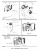
Install with beveled corner toward flasholder cutout HAND STRAP ASSEMBLY-169956 BACK ASSEMBI-YJ63842 SCREW (2)-136096 SE E F I GU R E 2 HINGE-l 63820 .. --=42====:--..:=é»$;-si=;==.; ee LEN s-164274 \ BAFFLE-163830 BAFFLE—I642I2 FIGURE TOP ASSEMBLY—l64680 Includes Lens and Baffle 3 BEZEL (Lef'r)—l642I4 BEZEL (Rightl—I642I5 LENS—I69077 ev e ‘ e _,§ . ._ ""61; we-\, I 5 -5‘ iw. ~~ ., _ Z 1* 13 3 3 if *"ae.»2f;§;‘Zf\;e FLASH GUARD-165234 ’ FIGURE 1 o VISI .
T é w|NDOw__]63829 SPRING-163838 SEEIFIGURE g_eUg'igl:r;\gSEMBLY (72 Tooth)-164683 9 l SPRING-163837 LEVER—l69066 ! I E . ..»- 4&3 owl , &§:§“"Ze Y ~" ~ ‘W ~ __ I“; .“‘.,A=,:\;?.§ -V q '>»\;,>- iv A MECHAN|SM PLATE AS5EMB|__Y__]64632 FIGURE ==,,.__._..;,i= j N <» 7 ~;* _ N,/Q’ %%% ? *9 ~+ i 1 ‘V l SHUTTER RELEASE LEVER ASSEMBLY-163844 .
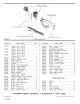
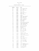
-~""~~¢ 1 _ CAP (4)-122863 SOCK ET (4)-121321 - POS STU § t, . : COVER ASSEMBLY-167133 . NECK STRAP ASSEMBLY-169976 FIGURE PART NO. 117220 136096 150601 152186 163803 163811 163820 163826 163829 163830 163831 163837 163838 163840 163842 163843 163844 163847 163848 163849 163850 164205 164210 164212 164214 164215 PART NAME Screw - Tap., Type B, pan hd, No. 2 x 3/16 . Screw - Tap., Type B, pan hd, No. 2 x 1/4 . . Screw - Tap., Type B, flat hd, No. 2 x 1/4 . . Screw - Tap., Type B, oval hd, No.
— A R ( —*——----» ’’’’ ~v— .. KS K) ~ —--e ‘fr ~ e»— ;._T_.... ."_D_ _...*-.I_ _. _ (?______._,.___,___i__>*, I w. s. s. # 374 (Supersedes #363) JULY NO. 1359 1963 (Supersedes #1345) APPARATUS SERVICE REPAIR INSTRUCTIONS KODAK INSTAMA TIC 100 CAMERA Repair at Divisions Effective immediately, the Kodak Instamatic 100 Camera is to be repaired by the Apparatus Service Department (Rochester and Divisions) and by all Warranty Service Shops.
is LIST OF PARTS for KODAKINSTAMATIC Quantity 100 CAMERA Part No.
TENTATIVE SERVICE INSTRUCTIONS for KODAK INSTAMATIC 100 CAMERA _-. _ ___4-,..
_-* TABLE OF CONTENTS Page SHUTTER 3 1.1 SPECIFICATIONS -------------------------- -1.2 SERVICE HINTS --------------------------- -- -------- ------------ -REMOVAL OF FLASHOLDER----------------- -REMOVAL OF SHUTTER SPEED LEVER -------- -REMOVAL OF SHUTTER BLADE SPRING ------- -- 1. 3 REMOVAL OF FRONT FROM cAMERA 1.4 REMOVAL OF TOP FROM cAMERA 1. 5 1. 6 1. 7 1.3 REMOVAL OF SHUTTER DRIVE LEVER SPRING--- FILM TRANSPORT 7 2.
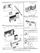
SERVICE INSTRUCTIONS KODAK INSTAMATIC 100 CAMERA Service instructions for this camera are separated on a functional basis for clarity and ease of use by the serviceman. The instructions include specifications and service hints. The service hints sections have been written in a condition, cause, and remedy format for easy reference. Service Tool #1065 - Kodak Demonstration Cartridge is useful in checking camera action during repair. 1 . 1. 1 i__i.
e) Failure to ash. Before investigating camera, batteries and ash bulb contacts should be checked. The ash circuit of Kodak Instamatic Cameras is unique. The drawing on the next page. Pictorially and schematically shows this circuit. loose battery cover. Cause - - Remedy 7.. form bottom vinyl covering down to make battery contact fit tighter and/ or install a new battery cover. The drawing shows the most effective position for forming the covering.
a i (H/% W > _ I 69 0z_~__“_'||| 89 JI| Oz_:_oI_w| d2 W30: M5303” HGUFSQV 2 < 5:3 EE U205 886 I ®OG>UN __®>U_ 2 < m H8: 282 E U5 gCM 23096 C30 m Ia UQUG>_UN @ Gaza $3300 OUNE USN I __®EO:mm__'_H ho m_UZmDOmw zogémzo <1 OO_ mS_
1--- 1.41 REMOVAL OF TOP FROM CAMERA a) Raise asholder V partially by depressing release bar. b) Pry up and remove metal rear top cover plate. It is cemented in position. c) Remove two screws holding top to frame. d) Remove flat head screw from side panel immediately above back latch. e) Film advance lever must be in the back (normal) position. Remove top from camera.
FILM TRANSPORT 2. 2.1 SPECIFICATIONS Film advance lever should operate smoothly and spring back fully when released. a) b) Film advance lever should cock shutter during first complete stroke of winding for each exposure. c) Film should advance as ‘film advance lever is actuated and stop at each proper location for exposure (numbers on film backing paper, perforations on film in demonstration cartridge).
c) Actuate film advance lever one full stroke to cock shutter and allow lever to return to the rest position under spring tension. Do g_c_>_t "sense" mechanism by moving sensing lever. Metering and sensing levers are now in correct position so that mechanism plate can be removed without disturbing them. d) Remove winding lever spring by advance lever.
-- 2. 5 REMOVAL OF METERING AND SENSING LEVERS a) Remove front and top from camera, instructions 1.3 and b) Remove mechanism plate, instruction 1.4. K M ‘! 2.3. c) Disconnect and lift off metering lever spring. Short leg of spring fits into "well" in frame, long leg contacts metering lever. d) '‘ _' M5-[ER|NG LEVER - Lift off brass spacer and metering lever.
D ._-3. 3. l HOUSING SPECIFICATIONS a) F lasholder must pop-up at least slightly when release bar on front of camera is pressed. b) Raising flasholder to flash position should be possible without undue force after flasholder has been unlatched by release bar. c) Flasholder lamp socket should accept an AG1 ash bulb or test lamp without excessive force and retain lamp has been inserted fully into asholder. d) Lamp should be released when ejector lever is moved to its maximumltravel. released.
‘rJ P Position a knife blade immediately below asholder release bar and form end of tang of release bar up toward top of camera. ' - A With knife blade in same position, pressin to compress tension of spring on front of asholder. Trim front edges of asholder to remove sharp edge and any burrs. from camera, trim front edges for entire length of flasholder. 3. 3 REMOVAL OF BACK ASSEMBLY If asholder is disassembled ' a) Open camera back.
f) If it is necessary to install a new taking lens, particular attention should be taken to observe lenses originally assembled to camera. Three different combinations have been used. If a new taking lens is installed, only assemble the new lens. All other parts should be removed and discarded. This includes retainer and lens (plano glass) in frame, and retainer and spacer in front.
f Q 0 4. 4. 1 CEMENT AND LUBRICANT r CEMENT - A&O #10-1168 or Minnesota Minning and Manufacturing (3l\/l) #PCl3-5'7 (Thinner-Toluol or Solvesso) Left and right finder bezels to front assembly. Black front top covering to top assembly. Rear top cover plate to top assembly. Front nameplate may also be attached with this cement or cement backing on plate may be activated with methyl ethyl ketone or chlorothene. ' 4.
In W. S. s. #384 (Addition) FEBRUARY 1964 NO, 1370 (Addition) - APPARATUS SERVICE REPAIR INSTRUCTIONS , KODAK INSTAMATIC 100, 300, 400 CAMERAS Deformed Right Battery Contact (Part No. 163847) V It has been observed that #17 0203 Wedge - Right Battery Contact 1s not being installed correctly. The part name and the installation drawing obviously were not sufficiently descriptive. ~ That is, it is molded H The function of this part, #170203 Wedge, is to act as a stop for the battery.
W. S. 5. SEPTEMBER 1963 #334 NO, 1370 APPARATUS SERVICE REPAIR INSTRUCTIONS KODAK INSTAMATIC 100, 300 and 400 CAMERAS Deformed Right Battery Contact (Part No. 163847) It has been observed that the right battery contact (Part No. 163847) has become deformed in some early models of the Kodak Instamatic 100, 300 and 400 Cameras. This deformation is caused by excessive compression of the contact, which then takes a set.
P- I INSTALLATION 1. Open battery cover and remove batteries. Reach into battery compartment with a suitable tool and form right battery contact toward battery cover. When contact is formed properly, approximately 1/4-inch from bottom of battery compartment, it will support a battery so that its base is ush with edge of mechanism plate and frame under vinyl wrapper. 2. Push a pointed tool into long side of wedge (Part No. 170203) with sufficient force to hold wedge during installation. 3.
W.S.S. #441 1%“ NOVEMBER NO. 1439 APPARATUS SERVICE REPAIR INSTRUCTIONS INSTAMATIC 100, 150, 300 and 400 CAMRAS Intermittent Flash Complaint ‘Occasionally, a Kodak Instamatic Camera owner may experience repeated, intermittent flash failure even though his camera proves to be satisfactory when subjected to all recommended tests. The purpose of this bulletin is to review the flash circuit and point out what may be the one logical explanation for his trouble.
A.S.R.I. # instruction book furnished with each camera directs the picture by SLOWZY pressing the shutter release all the way". While these instructions constitutedown good picture-making practice, intermittent flash failure may result if it is carried to an The user: . . . "Take the extreme. Many times a user will hold the shutter release partially depressed awating the desired pose of a subject or to record a particular event at a decisive moment.
AUGUST 1963 NO. 768427 Servicing the Kodak lnstumutic 100 Camera K (4 EASTMAN KODAK COMPANY Apparatus Service Department ROCHESTER 4, NEW YORK I 1,‘ ..__.-*-...
1'- (TABLE 1.. CONTENTS OF SHUTTER 5 ------------------------------- --------------------------------- --------- -REMOVAL OF TOP FROM CAMERA ---------------- -REMOVAL OF FLASHOLDER ---------------------- -REMOVAL OF SHUTTER SPEED LEVER ------------- -REMOVAL OF SHUTTER BLADE SPRING ------------ -- 1.1 SPECIFICATIONS 1.2 SERVICE HINTS 1.3 REMOVAL OF FRONT FROM CAMERA 1.4 1.5 1.6 1.7 1.8 REMOVAL OF SHUTTER DRIVE LEVER SPRING 2.
SERVICE INSTRUCTIONS KODAK INSTAMATIC 100 CAMERA of use by the serviceman. Service instructions for this camera are separated on a functional basis for clarity and ease in a condition, written been have sections The instructions include specifications and service hints. The service hints cause, and remedy format for easy reference. action during repair.
i-i— 1. SPECIFICATIONS 1._1 ' SHUTTER a) Shutter Speeds: » Daylight Speed, Flasholder down - Flash Speed, Flasholder up - Total Time: Total Time: 10 ‘ 19 to 16 milliseconds to 28 milliseconds b) Flash synchronization may be checked with a ashbulb. When viewing from film plane, a full bright aperture opening must be observed when bulb is ashed. Shutter release should be pressed extremely slowly for this check.
SHUTTER 1. b) Shutter will Cause - not trip and film advance lever will not return. shutter driver not "cocking". form end of film advance lever position. Remedy - so it will that move shutter driver farther and to the "cocked" c) Shutter held open. Cause - shutter trapped by shutter speed lever. Remedy - install new shutter speed lever or form upper arm of speed lever down toward bottom of camera that shutter tang cannot pass arm of speed lever when asholder is down.
1. SHUTTER 1.4 REMOVAL OF TOP FROM CAMERA a) Raise asholder partially by depressing release bar. b) Pry up and remove metal rear top cover plate. It is cemented in position. c) Remove two screws holding top to frame. d) Remove at head screw from side panel immediately above back latch. e) Film advance lever must be in the back (normal) position. Remove top from camera.
g. FIbM_TRA NSPORT 2.1 SPECIFICATIONS a) Film advance lever should operate smoothly and spring back fully when released. b) Film advance lever should cock shutter during first complete stroke of winding for each exposure. c) Film should advance as film advance lever is actuated and stop at each proper location for exposure (numbers on film backing paper, perforations on film in demonstration cartridge). d) Shutter release lever should be held by double exposure prevention device expostue location.
2. FILM TRANSPORT _ 2.3 REMOVAL OF MECHANISM PLATE FROM FRAME a) Remove top from camera, instruction 1.4. b) Remove front and flasholder from camera, instruction 1.3 and 1.5. c) Actuate film advance lever one full stroke to cock shutter and allow lever to return to the rest position under spring tension. Do not "sense" mechanism by moving sensing lever. Metering and sensing levers are now in correct position so that mechanism plate can be removed without disturbing them.
2. FILM TRANSPORT; 2.5 REMOVAL OF METERING AND SENSING LEVERS_ a) Remove front and top from camera, instructions 1.3 and 1.4. SENSING Disconnect and lift off metering lever spring Short leg of spring fits into "well" in frame, lon 8 le 8 contacts metering lever. l-EVER spacer and metering lever If a new metering lever is installed, it is necessary to check clutch assembly in mechanism plate.
3 H O U SING SPECIFICATIONS 1 a) Flasholder must pop-up at least slightly when release bar on front of camera is pressed. b) Raising flasholder to ash position should be possible without undue force after flasholder has been unlatched by release bar. cjl Flasholder lamp socket should accept an AG1 ash bulb or test lamp without excessive force and retain if lamp has been inserted fully into asholder. it, d) Lamp should be released when ejector lever is moved to its ma ximum travel.
3. b) Flasholder will HOUSING not "pop-up" at least 1/4-inch. or flasholder and frame. Cause - bind between front and flasholder actuate flasholder after each step and observe action. Remed y - per form the followin g steps in order and outward. grasp plate to which hand strap is attached and pull With a pair of pliers, forward toward front Loosen side screw near hand strap plate, hold flasholder tighten side screw again.
l 1 3 f) HO USI NG If it is necessary to install a new taking lens, particular attention should be taken to observe lenses originally assembled to camera. Three different combinations have been used. If a new taking lens is installed, assemble only the new lens. Remove and discard all other parts, including retainer and lens (plano glass) in frame, and retainer and spacer in front.
-1..-_ 5;._ 4.1 CEMENT CEMENT AND LUBRICANT or Solvesso) - A80 #10-1168 or Minnesota Minning and Manufacturing (3M) #EC-1357 (Thinner-Toluol Left and right finder bezels to front assembly. Black front top covering to top assembly. Rear top cover plate to top assembly. backing on plate may be activated with Front nameplate may also be attached with this cement, or cement methyl ethyl ketone or Chlorothene. 4.
'E{§@<@il@.11<§ N0.