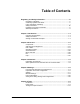
RP 30 LASER PRINTER OPERATOR'S GUIDE
Operator’s Guide KODAK PROFESSIONAL RP 30 Laser Printer P/N 6B7444 December 2002
© Eastman Kodak Company, 2002 All rights reserved. Contents of this publication may not be reproduced in any form without permission from Eastman Kodak Company.
Table of Contents Regulatory and Safety Information............................................................. iii Regulatory Compliance .................................................................................. iv Cautionary Symbols and Labels..................................................................... iv Laser Compliance and Safety ......................................................................... v Safety Precautions ..............................................................
Operator’s Guide Chapter 6 Production................................................................................. 6-1 Preparing the Equipment for Different Orders ............................................. 6-3 Order Processing ......................................................................................... 6-9 Print Modes ................................................................................................ 6-11 Printing File Print.................................................
Regulatory and Safety Information Contents Regulatory Compliance .................................................................................... iv EMC Compliance............................................................................................ iv CE Compliance............................................................................................... iv Cautionary Symbols and Labels...................................................................... iv Hot Surface Symbol................
Operator’s Guide Regulatory Compliance EMC Compliance NOTE: This equipment has been tested and found to comply with the limits for a Class A digital device, pursuant to Part 15 of the FCC rules. These limits are designed to provide reasonable protection against harmful interference when the equipment is operated in a commercial environment.
Regulatory and Safety Information Mechanical Hazard Symbol CAUTION: Moving parts. Avoid contact. Keep your hands, hair, loose clothing, and jewelry away from moving parts. Laser Compliance and Safety The KODAK PROFESSIONAL RP 30 Laser Printer is equipped with an Argon Ion Laser of Class 3B. To prevent damage caused by the laser beam, the laser is encapsulated. Because the laser is encapsulated the entire RP 30 Laser Printer is classified as a Class 1 Laser Device.
Operator’s Guide Certification Labels A B C Non-interlocked Panel Label D Aperture Label E vi KODAK PROFESSIONAL RP 30 Laser Printer
Regulatory and Safety Information Laser Source Label F Locations of Laser Safety Labels B C (side) A E F D KODAK PROFESSIONAL RP 30 Laser Printer vii
Operator’s Guide Safety Precautions Legal Notice The RP 30 Laser Printer is designed for operation in conformance with all local safety regulations. Follow all safety regulations, warnings, and instructions on machine labels. Failure to observe these regulations may result in personal injury or damage to the equipment and working area. The manufacturer and service provider will not assume any responsibility for accidents and damage resulting from incorrect operation.
Regulatory and Safety Information Handling of Processing Chemicals Disposal of Chemicals and Containers Effluent Management IMPORTANT: Regulations and requirements regarding the proper disposal of photographic processing effluents vary by region and by locality.
Operator’s Guide Safety Precautions for the Handling of Chemicals WARNING: Be certain to follow these guidelines for the safe handling of chemicals in the equipment working area. General Guidelines • Be sure that all persons operating the equipment have a complete set of instructions for the handling of dangerous substances. • Be sure that all persons operating the equipment have training on the handling of dangerous substances at least once a year.
Regulatory and Safety Information Warranty Information The following warranty information pertains to equipment that is installed in the United States only. For equipment installed in countries other than the United States, the terms and conditions of the new equipment warranty are provided by the Kodak company in the country in which the sale is finalized, or by a Kodak-appointed distributor in those countries where Kodak does not have direct sales representation.
Operator’s Guide Limitations Warranty service is limited to areas within Kodak’s established marketing centers in the contiguous United States, the island of Oahu in Hawaii, and some areas of Alaska. This warranty does not cover circumstances beyond Kodak’s control; it does not cover service or parts for any attachments, accessories, or alterations not marketed by Kodak, or to correct problems resulting from their use.
Chapter 1 Introduction Contents Using the Documentation...............................................................................1-3 Structure .......................................................................................................1-3 Text Styles....................................................................................................1-3 Notices..........................................................................................................1-3 Safety Precautions ......
Operator’s Guide 1-2 KODAK PROFESSIONAL RP 30 Laser Printer
Introduction Using the Documentation Structure This Operator’s Guide contains information about: • Safety precautions • Machine settings • Print configurations • Production • Maintenance Text Styles In this guide, bold print indicates screen or button designations. Examples: “Touch OK to validate the displayed text and close the Input screen.” “Touch Network print to process network orders.” Italic print indicates cross-references.
Operator’s Guide Safety Precautions See the Regulatory and Safety Information in the front of this guide for details about: • Electrical precautions • Operation of the equipment • Disposal of the equipment • Handling and storage of processing chemicals • Laser safety Follow all safety regulations, warnings, and instructions that are on equipment labels and in the guide.
Chapter 2 Overview Contents Components............................................................................................................. 2-3 Product Description ...........................................................................................2-5 Image Editing.....................................................................................................2-5 Functional Procedure ........................................................................................
Operator’s Guide Settings Menu (without Machine Settings) ..................................................... 2-30 Settings Menu (with Machine Settings) .......................................................... 2-31 Test Menu ....................................................................................................... 2-32 End of Work Menu .......................................................................................... 2-33 Status Information / Help Menus.............................
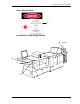
Overview Components The KODAK PROFESSIONAL RP 30 Laser Printer consists of three main components. 2 1 3 1 Main computer – controls the complete program and generates print data. A touch-screen monitor is connected to the main computer. 2 Printer – prepares and transports the paper size to be printed and uses a laser to print the digital image on paper. 3 Paper processor – includes a connected sorter and a deposit tray for the prints.
Operator’s Guide 5 2 3 4 6 7 8 1 10 12 9 11 13 1 Print engine with laser fiber and laser module 8 Main switch, ground fault indicator (GFI) switch 2 Touch-screen monitor 9 Drain valves for the chemical overflow 3 Main computer 4 Wet section with racks, crossovers, and chemical filters 10 Right-hand paper magazine 11 Lane distributor 5 Paper outlet with integrated densitometer 12 Transport unit 6 Dryer 13 Left-hand paper magazine 7 Order sorter 2-4 KODAK PROFESSIONAL RP 30 Laser Printer
Overview Product Description The RP 30 Laser Printer provides convenient and quick printing of digital images. The image files are transferred to the RP 30 Laser Printer from either: • Network (workstation), or • Data carriers − diskette − ZIP disk − CD-ROM or Smart Media card (by way of PCMCIA adapter) NOTE: It is the customer’s responsibility to provide for a network and/or a workstation and to provide for its connection.
Operator’s Guide Functional Procedure The RP 30 Laser Printer performs the following functions to process print orders. • Loads the image information • Cuts the paper • Transports the paper • Edits the images, if necessary • Exposes the images • Distributes the paper to the appropriate lane to the processor • Processes the images • Deposits the prints in the sorter These functions are described in the following Printing Sequence section.
Overview Printer The printer transports the cut paper (1) to the print engine (2), exposes the paper to the laser beam, and advances it through the transport unit (3) up to the lane distributor (4). The back print (5) is applied in the lane distributor. The lane distributor transports the print to the paper processor. 3 4 5 2 1 Paper Processor The exposed paper advances through the processing solutions (1), which include the developer, bleach-fix, and stabilizer.
Operator’s Guide Sorter After drying, the prints exit from the print chute (1) into the sorter (2), where they are sorted by orders and stacked in trays. • If a print order exceeds the capacity of one tray (a maximum 43 prints), the sorter automatically switches to the next tray without terminating the print order. • Splices in the paper rolls are cut separately and the respective pieces of paper are deposited in the print order stack. • Large prints are deposited on the large print deposit tray (3).
Overview Densitometer The built-in densitometer (1) above the dryer automatically measures the test print.
Operator’s Guide Switching On the Equipment IMPORTANT: Before switching on the equipment, insert the paper magazines, which are loaded with the appropriate size paper. The two methods of starting the RP 30 Laser Printer are: • Automatically, by way of the integrated timer – the preferred procedure • Manually, by pressing the ON button – the alternate procedure The conditions for switching on the equipment are: • The equipment was not previously switched off by way of the main circuit breaker.
Overview Manual Switch-On 1. Switch on the main circuit breaker (1). 2. Press the ON button (2), if necessary. The ground fault interrupter (GFI) switch below the main circuit breaker always remains on.
Operator’s Guide System Start After automatic or manual switch-on, the equipment heats the solutions and the dryer to nominal temperatures.
Overview Start Screen After you log in, the menu bar with the five main menus appears. • Print mode offers all functions for image editing and printing (see Production, Chapter 6). • Settings lets you create the print configurations and enter machine-specific parameters (see Settings, Chapter 4). • Tests lets you test the equipment prior to the production start and during production (see Tests, Chapter 5). • End of work lets you shut down the machine completely or partially (Sleep mode).
Operator’s Guide End of Work Changing Users To change users, you must first log out. 1. Select End of work in the menu bar. 2. Touch Change user. 3. Touch Logout.
Overview Work can continue only if a user follows these steps to log in again. 1. Select the name of the next user. 2. Enter the password (four numbers). 3. Touch Login. If a different language is allocated to the new user in the machine setup, all text is displayed in this language.
Operator’s Guide Manual Shutdown 1. Select End of work in the menu bar. 2. Touch Shutdown. 3. Change the start information in the display, if necessary: • Change Timer Change the date / time for the next start in the opening screen. • Next Login Select the user for the next switch-on. NOTE: Changes to the start time and user are only valid for the next start. Permanent changes are only possible by way of the equipment settings.
Overview 4. Perform the daily maintenance procedures (see Daily Maintenance in Chapter 8). 5. If unprocessed orders exist, answer the query as to whether they should be saved. Orders that are not saved are lost. The equipment is now shut down and switched off. Emergency Reset CAUTION: The main circuit breaker is for emergency reset only.
Operator’s Guide Operating Controls Button and Lamp on the Main Computer There is one button and one lamp on the main computer: • ON button (1) If the system is shut down by End of work – Shutdown, it remains in the timer mode until the next automatic startup. If you must switch on the system before the next automatic startup time, press the ON button. The system will then start up. Additionally, you can press the ON button to initiate a reset.
Overview Touch-screen Monitor The operation of the equipment is menu-driven by a touch-screen monitor. You activate the functions by touching the touch-sensitive buttons on the screen. Specifications: • 15-inch LCD screen • SVGA resolution 1024 x 768 pixels • Screen-refresh frequency > 75 Hz For more information, see Screen Structure on Page 2-20, Touch-sensitive Buttons on Page 2-23, and Menu Overview on Page 2-27.
Operator’s Guide Screen Structure 9 NOTE: This operator’s guide refers to the touch-sensitive fields of the touch-screen monitor as “buttons.” The screen is divided into different areas: 1 2 3 4 5 6 7 Information area Fixed buttons (i, ?, and Stop) Status line Active screen Buttons Pop-up window, if available (not shown in the above example) Menu bar with five main menus The areas 1, 2, 3, and 7 are always displayed. However, the menu bar (7) cannot always be used.
Overview Information Area The Information area includes the fixed buttons (i, ?, and Stop) and the status line. Because the fixed buttons are always accessible, you can open the Info and Help screens at any time. For more information, see Info on Page 2-34 and Help on Page 2-40. The fixed buttons are described below.
Operator’s Guide All error messages are saved. You can view a list of the messages by touching i, then Error list. Below is an example of an error list. For more information, see Correcting System Conditions, Chapter 7.
Overview Touch-sensitive Buttons NOTE: Only one screen is active. It is not possible to open several windows at the same time. The buttons in areas of the screen other than the information line (i, ? and Stop) change with the functions of the associated menu.
Operator’s Guide 1. Select the desired configuration from the list. 2. Touch OK. Pop-up Windows Pop-up windows open on the active screen if you must make a confirmation or perform an action: • A Reset pop-up appears when you must execute a reset to resolve an error. • An Error pop-up appears when either incorrect (or inconsistent) entries or system errors occur. You must remove these errors before work can continue. • A Warning pop-up appears if a risk of data loss occurs.
Overview • An Info pop-up appears to provide additional status information. • A Query pop-up appears to let you avoid potential problems.
Operator’s Guide Input Screen When you must enter text, numbers, or special characters, the Input screen opens. • The image of a keyboard includes national special characters in accordance with the selected keyboard allocation. (For the selection of the keyboard allocation, see User Interface in Chapter 4.) Touch a button to select the corresponding character.
Overview Numeric Keypad Use the numeric keypad in the display to enter the desired number and touch OK to confirm. Menu Bar The main menus are always accessible, except when either a pop-up window is open or the Help screen is open. Menu buttons that appear gray indicate that the function is not available. The structure of the menus is described in the next subsection, Menu Overview.
Operator’s Guide Menu Overview Main Menus You can open the following main menus from the menu bar: • Print mode • Settings • Test • End of work NOTE: Pricing is not available. Other screens are available by pressing i and ?: • Status information • Help All menus and associated screens are outlined on the following pages.
Overview Print Mode Menu KODAK PROFESSIONAL RP 30 Laser Printer 2-29
Operator’s Guide Settings Menu (without Machine Settings) 2-30 KODAK PROFESSIONAL RP 30 Laser Printer
Overview Settings Menu (with Machine Settings) ar KODAK PROFESSIONAL RP 30 Laser Printer 2-31
Operator’s Guide Test Menu 2-32 KODAK PROFESSIONAL RP 30 Laser Printer
Overview End of Work Menu Status Information / Help Menus KODAK PROFESSIONAL RP 30 Laser Printer 2-33
Operator’s Guide Additional Screens These screens are accessible at any time.
Overview Info Printer The Info Printer screen is a graphic representation of the paper transport and shows the number of prints at the individual stations in the printer. This screen also contains the width, surface, and residual length for each of the two paper magazines. When an error occurs, the corresponding component of the printer is displayed in red. To return to the main Info screen, touch Back.
Operator’s Guide Info Paper Processor The Info Paper Processor screen is a graphic representation of the solution tanks and the dryer, and shows the number of prints currently in the processor. This screen displays: • Order numbers for the orders in the paper processor • Time remaining until the last print is exited • Nominal and actual temperatures of the solutions and the dryer When an error occurs, the corresponding component of the paper processor is shown in red.
Overview Info Order The Info Order screen displays the number of orders not yet printed, including network orders and orders stored for file prints (backup). To return to the main Info screen, touch Back.
Operator’s Guide Version Info The Version Info screen shows: • Current versions of the installed software and firmware • Serial number of the hardware • License ID of the machine To return to the main Info screen, touch Back.
Overview Error List All error messages shown in the status line are saved. Touch i, then Error list to view the error messages. The list shows the error messages with the date and time of occurrence. • Disable Display all errors if the error list only shows the errors encountered since the last start or reset. • If the complete error message is not displayed in the error list, touch the message to display the complete text below the error list.
Operator’s Guide Help You can access Help from every screen that has a ? in the information area (see Screen Structure on Page 2-20). NOTE: For operations requiring significant computing time, the Help window is not displayed immediately. A pop-up window opens with the following options: • Waiting or • Cancel Help text displays for the screen in which you touched ?. The display includes links to the Help texts.
Chapter 3 Chemicals Contents Contents ................................................................................................................... 3-1 Preparation of Chemicals ....................................................................................... 3-3 Rinsing the Tanks..............................................................................................3-4 Mixing the Tank Solutions .................................................................................
Operator’s Guide 3-2 KODAK PROFESSIONAL RP 30 Laser Printer
Chemicals Preparation of Chemicals CAUTION: A risk of injury is possible if the wet section cover is unlocked (PUSH is pressed) unintentionally. The lock engages only in the vertical position. To open the cover: Carefully lift the cover until the lock engages. To close the cover: 1. Support the cover with one hand. 2. Press the unlocking lever (PUSH) and carefully close the cover.
Operator’s Guide A water temperature of approximately 30°C (86°F) is recommended for the preparation of the individual tank fillings. The chemicals can be mixed directly in the machine tanks. CAUTION: To prevent contamination of the chemistry, always fill the tanks in the following order: SB Ö BX Ö CD Thoroughly rinse the containers used for the preparation with cold water after each preparation of a solution. CD BX SB1 SB2 SB3 SB4 Rinsing the Tanks 1. Open the paper processor cover. 2.
Chemicals Mixing the Tank Solutions The instructions assume that you are mixing the fresh-tank solutions directly in the processor tank. CAUTION: Use cold water when you mix solutions to prevent you from unnecessary exposure to fumes that can be released at higher temperatures. Handle all chemicals carefully. When you mix solutions, wear goggles or a face shield, a protective rubber apron, and protective gloves made with either neoprene or nitrile rubber.
Operator’s Guide Bleach-Fix You can mix the working bleach-fix tank directly from the two-part concentrates. Use two EKTACOLOR Processing Cartridge 75 units to supply the two bottles of each of the two concentrate solutions. CAUTION: Be careful to avoid contamination of the developer with bleach-fix. 1. Add 12.7 L water to the tank. 2. Add the entire contents of two bottles of bleach-fix concentrate, Part A (labeled BX-A). 3.
Chemicals Installing the Racks and Bringing the Tank Solutions to Temperature When you fill the tanks with the new mixes, they will appear only partially filled. When you reinstall the racks in the tanks, the racks will displace more solution volume to fill the tanks. 1. Install each rack by slowly lowering it into the tank; the rack will displace additional volume to fill the tank and partially mix the solution. 2. When you have reinstalled all the racks, verify that all tanks are filled with solution. 3.
Operator’s Guide 4. Put the EKTACOLOR Processing Cartridge in the docking station with the sticker facing up. 5. The preparation of the replenishers starts as soon as the docking station is closed. During this procedure, the door is locked mechanically and the LED on the left side of the docking station illuminates steadily. IMPORTANT: There should always be a cartridge in the docking station to reduce oxidation. Once the LED is turned off, the cartridge may be removed and replaced by a full one.
Chapter 4 Settings Contents From the Order Receipt to the Finished Print ...................................................... 4-3 Administrator .....................................................................................................4-3 Operator ............................................................................................................4-4 Preparation of the Print Configuration.................................................................. 4-5 Settings.......................
Operator’s Guide Print Configurations ............................................................................................. 4-40 Creating, Editing, and Deleting Configurations............................................... 4-42 Creating a New Configuration.................................................................... 4-42 Creating a New Configuration Based on an Existing One......................... 4-42 Editing a Configuration..................................................................
Settings From the Order Receipt to the Finished Print Administrator Administrator actions Definition of settings, configurations, users Initiated using the following buttons Settings for the automatic Startup by the timer: start times, first user, calendar with off-days and company holidays Settings Machine settings Startup Configuration settings: They are used as the basis for the print configuration.
Operator’s Guide Operator Operator actions Logon, preparing the equipment, test, and order editing 4-4 Button or Action User Logon Shutdown Change user Select a name for the operator Enter the Password Touch Login Preparing the RP 30 Laser Printer for an order Prepare paper magazines (insert paper, code magazine) and insert them Testing the paper and the equipment: IMPORTANT: Use MBL paper for the 1st PBL.
Settings Preparation of the Print Configuration Settings Machine Settings Settings Paper surfaces Machine Settings Paper settings Define user ? Settings of cut lengths Import indexprint layouts Test Perform MBL/PBL with laser point Import combiprint layouts Print settings Order KODAK PROFESSIONAL RP 30 Laser Printer 4-5
Operator’s Guide Settings Machine Settings Surfaces edit new Set/change switch Set switch for cassette coding Change PFDF surface Select PFDF surface e.g. Switch 5 Switch 6 ⌧ e.g. "fine grained" OK OK Save as Save Enter name Return e.g.
Settings Paper settings edit new Select paper width in mm Set switch for cassette coding Set switch for cassette coding e.g. Switch 1 Switch 2 Switch 3 Switch 4 ⌧ ⌧ ⌧ Save as Save Enter paper width in mm Return OK Settings of cut lengths e.g. "152" Return edit new Select paper width in mm Enter paper width in mm Edit OK OK Save Save e.g.
Operator’s Guide Settings Print settings Order Select configuration edit new Select film mask Select film mask OK OK Select film type Select film type OK OK Select type of config. Select type of config. OK OK Select PpF Select film mask OK OK Select Index print /off Select PpF OK OK Select back print/off e.g. "Flie print" e.g. "File print" e.g. "Single" e.g. "1" e.g. "Index_152_ 102 neutr." e.g.
Settings Select index print/off Adjust correction/off OK OK Select back print/off Select auto save/off e.g. "off" e.g. "off" OK OK Adjust correction/off Select auto save/off OK Select border new/off Select border new/off e.g. "10" OK Select exposure/off OK Select (FF) Paper configuration/off e.g. "Front print 1" By "File print" from here other config. menus e.g. "Prestige d 152" OK OK Select exposure/off Select (FF) Paper length/off e.g.
Operator’s Guide Select FF Paper length/off Select P Paper configuration /off OK Fill print size to paper OK Select FF adjust to ... Select P Paper length/off OK Adjust shorter side OK Select P adjust to ... Select P Paper configuration /off Adjust longer side OK OK Save as Select P Paper length/off Enter name OK OK Select P adjust to ...
Settings Settings Settings can only be modified if there is no paper in the transport of the printer and paper processor. The Settings menu item is disabled as long as paper runs through the equipment. When all prints of the current order are in the paper processor, you can touch Stop to stop the running operation. The Settings menu will then be available. To open the Setting screen, touch Settings on the menu bar.
Operator’s Guide Entering Names If entry of names is required, the Input screen opens automatically. Names of configurations have a maximum length of 30 characters. Special characters are possible, with the exception of quotation marks. Characters that are typed appear in the blue field and in the button above the image of the keyboard. This lets you see immediately how much of the entered text will appear in the button when you select it from a list or drop-down menu.
Settings Entering Numbers If entry of numbers is required (the numeric user password, for example) the numeric keypad opens automatically. Enter the value and press OK.
Operator’s Guide Machine Settings Types of Settings To open, touch: • Settings • Machine settings The machine settings are divided into two sections: Configuration and Machine. The configuration settings are saved and loaded together with the print configurations. Configuration • Surface and Paper settings Set the switches according to the paper magazine coding for the surfaces (5-6) and the paper widths (1-4).
Settings Machine • User interface for the national settings • User manager to create users with name, password, and rights of access • Settings for the automatic Startup, like workdays with start times / first user, calendar (holidays, company holidays) • Settings for the printer and paper processor • Settings for the printer and paper processor • Production balance Impact, sharpness - edges, saturation, sharpness - grain, detail contrast, color / density corrections • Network orders Settings to receive an
Operator’s Guide Defining Surfaces 1. Touch: • Settings • Machine settings • Surface • New 2. Select PFDF surface. This is a list of the standard PFDF surfaces (important for network orders), such as Glossy (F), Matte (N), or Lustre (E). 3. Activate Switch. The switches 5 and 6 define the name of the paper surface. (See Coding the Paper Magazine on Page 4-19.) 4. Select Save as. Enter the name of the new surface configuration. Save is only displayed if the screen was opened using Edit.
Settings Defining Paper Settings 1. Touch: • Settings • Machine settings • Paper settings 2. Touch New to create a new paper width 3. Select a configuration from the list and click Edit.
Operator’s Guide 4. Activate the appropriate Switches. The switches 1 to 4 define the paper width. (See Coding the Paper Magazine on the next page.) 5. Select Save as. Enter the name of the new paper setting. Save is only displayed when the screen was opened using Edit. The total number of paper widths usable without modification is 16. A maximum of four different surfaces can be used in the same way for all widths.
Settings Coding the Paper Magazine The paper magazine is coded for the paper width (1-4) and the surface (5-6) in use. The meaning of the coding is described below. Slide closed ■ Slide open Paper Width Width Indicators 1 2 3 Surface Indicators 4 5 3.25 inch (82 mm) 3.50 inch (89 mm) 3.75 inch (95 mm) 4.00 inch (102 mm) 4.75 inch (120 mm) GLOSSY 5.00 inch (127 mm) MATTE 6.00 inch (152 mm) CUSTOM1 6.50 inch (165 mm) CUSTOM2 7.00 inch (178 mm) 8.00 inch (203 mm) 8.
Operator’s Guide Defining Cut Lengths 1. Touch: • Settings • Machine settings • Cut length 2. Select New cut length / Delete cut length to update the list of created cut lengths. The range is 82 to 305 mm. 3. Select Save. The cut lengths defined here are offered in the selection boxes of the order configurations.
Settings User Interface 1. Touch: • Settings • Machine settings • User interface 2. Select the data for the user-specific settings: • Language German, English, French, Italian, Spanish, Japanese, etc. • Keyboard for the input screen on the touch screen • Beep Touch on/off Acoustic signal after a button has been touched • Preview freq. Movement frequency of the images in preview. The fastest possible frequency is preset (3 seconds).
Operator’s Guide User Administrator: Defining Users and User Rights Enter the settings under User interface first, because they are needed for the userspecific settings. Any number of users can be defined, but the following two are required: • Administrator with user rights for all functions, except service • Service with unlimited rights for all functions, including service 1. Touch: • Settings • Machine settings • User manager 2. Touch New. The next screen opens.
Settings − Edit Select the user in the list and touch Edit to change the corresponding settings. The next screen opens. − Password, Repeat The password (maximum four digits) is defined for new users by double entry. An Old password of an existing user can be changed in the same way. − Language, Keyboard, Preview frequency, Beep touch The entries made in the User interface are displayed (see the previous page). These general settings can be adjusted for each individual user.
Operator’s Guide − User rights The administrator can combine the user rights listed in the following table individually for each user in order to create a user profile.
Settings Startup: Defining the Start Time / Standard User (Timer) 1. Touch: • Settings • Machine settings • Startup 2. Define: • Automatic Start When you enter the start times, allow approximately one hour to preheat the solutions and dryer to the correct operating temperature. Set Off for off days. • Sleep mode / Shutdown In sleep mode, the system is shut down with the Shutdown option in the End of work menu. The main computer remains on for checking statistics.
Operator’s Guide Calendar: Defining Off Days 1. Touch: • Settings • Machine settings • Startup • Edit calendar 2. Select year / month with the arrow keys. 3. Define off days; for example, company holidays • Black for workdays • Blue for off days 4. Touch OK.
Settings Installing the Software 1. Touch: • Settings • Machine settings • Install software 2. Touch Load CD. 3. Touch Install. Check if the settings were saved on an external data carrier. If No, the operation is stopped. If Yes, the input screen opens. Enter the serial number. The software is installed and enabled. Then a new start is enforced. 4. Update the system software. If the system does not function correctly afterwards, restore the status before the update with the previous version.
Operator’s Guide Printer Settings 1. Touch: • Settings • Machine settings • Printer 2. Enter the required information: • Overlapping Indicate by how many percent the digitized image is calculated greater than the paper to be exposed. The range is 0 to 10%. • Master Paper Define the paper used most frequently as master paper. The MBL is performed on this paper.
Settings Paper Processor Settings Setting the Replenishment Rates NOTE: It is not possible to modify the individual replenishment rates. The rates for Color Developer, Bleach-Fix, and Stabilizer can only be increased or reduced together at the same ratio. If one of the replenishment rates is changed, the values of the other two solutions are changed in proportion. CAUTION: If possible, do not change the preset (default) values. Modified values should be reset to standard, if required. 1.
Operator’s Guide • At the first system startup or after the RP 30 Laser Printer has not been used for some days, you must enter an initial value. Touch Activate normal repl. After 5 operating days, the replenishment will be in accordance with the throughput. Replenishment Rates Solution Time in seconds Replenishment rates Developer 33 60 ml/m Bleach-fix 33 100 ml/m Stabilizer 69 60 ml/m + 140 ml/m water 2 2 2 2 Production Balance – Digital 1.
Settings Changes in the parameters shifts the printed results into one direction. For this reason, only experienced operators should modify parameters. • The settings influence all orders. • Modifications are only effective after a new start. • These settings are not considered in the backprint as the productions balance defines the basic balance (0-value).
Operator’s Guide Impact Changes in the correction effect (only influences the color and density regulators): • Presetting: 100% • Range: 10 to 200% The presetting of 100 should result in a correction density step of about 0.01D and a color step of about 0.03D to 0.04D on the paper (always depending on the paper gradation). The parameter changes are linear; a value of 50 halves the effect and a value of 200 doubles the effect.
Settings Sharpness of Edges This parameter is used for the correction of light/dark transition along edges, such as a window in a building. • Shifting towards + The light/dark transition is emphasized, the edge appears sharper. • Shifting towards – The edge appears softer. The impression of sharpness depends on the print size and the paper surface; a special correction configuration should be set up for each print format and surface. • Sharpening: Only effective if there is sufficient contrast.
Operator’s Guide Sharpness of Grain This parameter has a similar effect as Sharpness of edges, however on smaller structures (< 1 mm), such as on hair in portraits or on grass. • Shifting towards + Fine structures appear sharper. • Shifting towards – Fine structures appear softer. • Fine structuring: If the value is increased, fine details become even sharper (such as highlights in the night), but homogenous areas show noise effects.
Settings Digital Order Settings 1. Touch: • Settings • Machine settings • Network orders 2. Enter the required information. Remote Order File Print Defines an external storage location within the network where image files for the File print / Remote order print mode are stored and can be accessed by the RP 30 Laser Printer. (Access by way of ). When File print / Remote orders is started, the system automatically connects to the specified computer / drive.
Operator’s Guide Remote Order Autosave Defines an external storage location within the network, where to the RP 30 Laser Printer copies and saves the image files if the Autosave function is activated. • Computer name See Remote Order File Print above. • Resource name See Remote Order File Print above. Network Orders These parameters allow automatic printing of network orders in print breaks (no activity by the operator within a certain adjustable time).
Settings PDM (D-Bridge) Information about the PC (PDM Server) on which the PDM Software is installed (required for network orders): • Address or name Name or IP address • Port no. (Standard is 5001 or pfdmcom, if the corresponding input in the SERVICES file exists) PFDF (Photofinishing Data Format) is a standardized format for order data to be used in networks. The PDM (PFDF Data Manager) manages the order files.
Operator’s Guide Other Settings 1. Touch: • Settings • Machine settings • Other settings 2. Enter the following information required for the production: • Lab ID Equipment-specific identification number within a laboratory. Can be included in the backprint. Permissible range: 160 to 169 • Lab name Free name. Can be included in the backprint. • Order no. − Manual The order number displayed for the operator can change the printing of an order in File print mode.
Settings • Check PpF If this parameter is activated a warning message will be displayed as soon as the number of prints (PpF) entered for an order exceeds the value defined in the Max. PpF field. Work continues as soon as the warning is confirmed. There is no automatic correction for PpF. • Max. PpF Maximum number of prints per frame that will be printed without a warning display. • Backprint Activation of the backprint for the File print mode.
Operator’s Guide Print Configurations 1. Touch: • Settings • Print configurations 2. Enter the required information.
Settings All the settings required for creating the desired print size (for example, 9 x 13) including further options (such as backprint) are stored in the print configurations. For this, the following configurations are defined: • Paper • Backprint • Correction • AutoSave • Front print • Order Single, Package, Reproduction Order configurations are combined on the basis of the other configuration types. For this reason, these sub-configurations must be created first.
Operator’s Guide Creating, Editing, and Deleting Configurations The various configuration lists contain all related sub-configurations. Creating a New Configuration 1. Touch New. A screen appears with the existing preset values. In some configuration menus the Film mask field is displayed. Here the meaning of this term is “image source.” For the RP 30 Laser Printer, only one image source can be set up, which is File print. This parameter has a fixed allocation and cannot be changed. 2. Enter the settings.
Settings Editing a Configuration 1. Touch the configuration. 2. Touch Edit and modify the settings in the next screen. 3. Save. Deleting a Configuration 1. Touch the name in the configuration list and touch Delete. 2. If the configuration is used in a main configuration, you do not have to delete the main configuration. Instead, select another configuration to replace the deleted one. • Sub-configuration used in the order configuration • Order configuration Single used in the order configuration Package 3.
Operator’s Guide Paper Configurations A paper configuration consists of a paper setting for each (width) and a surface. The cut length of the paper is kept independent of the paper configuration, and it can be assigned to an order configuration in the Order menu. Creating a Paper Configuration 1.
Settings 2. Select from the Paper Settings and the Paper Surfaces. The paper settings and surfaces created before in the Machine settings are now offered. • Switches for the paper magazine change • Switches 1 to 4 define the paper width • Switches 5 and 6 define the surface • The switch positions are defined under Settings / Machine settings / Surfaces and Paper settings. They cannot be modified here. IMPORTANT: Each switch combination of the magazine switches may only be used ONCE. 3.
Operator’s Guide Backprint Configurations Settings apply to the print mode File print. For Network orders, the backprint is part of the image individual order data. The print field is 2 x 40 characters. Positions not used are filled with points. 1. Touch: • Settings • Print configurations • Backprint • New or Edit 2. Select File print from Filmmask.
Settings Here the meaning of the term "Film mask" is "image source." For the RP 30 Laser Printer, the image source File print is fixed and cannot be changed. 3. Create backprint text with a combination of the machine-generated parameters and additional operator comments. a. Add or Remove parameters. b. If Free text was selected, touch the field of the same name and enter the text. The preview of the backprint text and the indication about still-available blanks are constantly updated. 4.
Operator’s Guide Here is some additional information about some of the parameters. Print date/time is printed for the formats selected under Machine settings / User interface. Color / density corrections prints the corrections of the correction configuration plus the manual corrections. Because of this data in the backprint, exact reorders are possible. The corrections are entered in the Production balance menu. Digital is considered a basic balance for the File print mode.
Settings Correction Configurations The options the RP 30 Laser Printer offers to improve the image can be combined in special configurations, named and saved, for certain subject groups (snow shots) or certain customers. Correction configurations are only effective in the File print mode. 1. Touch: • Settings • Print configurations • Corrections • New or Edit 2.
Operator’s Guide For explanations of the function of these corrections, see Production Balance – Digital on Page 4-30. These corrections appear in the backprint if backprint text was selected. See Backprint Configurations on Page 4-46.
Settings Autosave Configurations Autosave configurations are used to save image files on a data carrier. The aspect ratio is kept. A folder is set up for every order on the data carrier: • The folder name = order name_date/time (for example: 001_0208051130). • The files copied into this folder are named as follows: File name_internal image number.format (for example: Testprint_0001.bmp) 1. Touch: • Settings • Print configurations • Autosave • New or Edit 2. Select the type of Autosave configuration.
Operator’s Guide Autosave fixed • File format In this mode, the files are always saved in the format bmp. • Drive Selection of a local drive: floppy disk. • Quantity Enter the number of image files that are to be saved on the selected medium. As the storage capacity of the selected medium cannot be changed, the resolution of the image is automatically adapted to fit the desired number on the medium.
Settings Autosave quality • File format bmp or jpg with various compression factors. • Drive Selection of a local drive (floppy) or external drive. The folder defined and shared in the menu Settings / Machine settings / Network orders / Remote orders: Autosave is offered. • Resolution Four different resolutions are offered.
Operator’s Guide PDM (D-Bridge) • Resolution and File format as in Autosave quality. The address of the PC where the PDM server (D-Bridge) is installed has been defined before. See Network Orders on Page 4-36. • CD, Internet Upload, Normal If one or more of these fields is selected, the stored image files in the corresponding order file are marked. This marking allows an automatic further processing of the files by way of the programs connected with the PDM, such as writing to a CD. 3.
Settings Front Print Configurations Front print configurations let you expose free text on the front of the print. 1. Touch: • Settings • Print configurations • Front print • New or Edit 2. Select Font, Size and Position. 3. Touch Font color or Background color.
Operator’s Guide 4. Select the color and press OK or Select the color and press New. Modify the red, green, blue color parts in the next screen to create the desired color and press OK twice. 5. Select Save or Save as.
Settings Order Configurations As the sub-configurations are accessed in the order configurations, they must always be created first. A created sub-configuration can be used in any number of order configurations. 1. Touch: • Settings • Print configurations • Order • New or Edit 2. Select Film mask. The software is used for configuration with and without a scanner. The term "Film mask" in the RP 30 Laser Printer stands for "Filter". The associated configurations, previously created, are listed.
Operator’s Guide 3. Select the Configuration type. • Single A single order configuration. See Creating a Single Configuration on the next page. • Package Several single order configurations are combined in one package to print different sizes from one Image file in one step. This means that single order configurations must be created before a package can be created. See Creating a Package Configuration on Page 4-60.
Settings Creating a Single Configuration 1. Set the Configuration type to Single. 2. Select Film mask: File print. 3. Select sub-configurations or set to OFF. 4. Select PpF (number of prints per frame). The default value is 1. 5. Enter the Border size, from 4 to 60 mm, or 0 for borderless. 6. Specify Paper configuration and Cut length. 7. Select a crop: a. Fit image to paper (standard): The image remains unchanged and the border is added. b.
Operator’s Guide Creating a Package Configuration You can use any combination of order configurations. If a configuration with more than two paper widths is used for printing, you may be asked to change the paper magazine. 1. Select Film mask and Film type. In the RP 30 Laser Printer, both terms correspond to the term Image source. 2. Set the Configuration type to Package. 3. Select sub-configurations or set to OFF. 4. Select Change PpF (number of prints per frame). The default value is 1. 5.
Settings Reproduction Order configuration for image files that are to be printed without automatic image improvement. Printing is without preview. The configuration cannot be changed. The image is printed in the middle of a large size (400 dpi), e.g. for CD Inlays. 1. Set Film mask and Film type on File print. 2. Set Configuration type to Reproduction. 3. Select Backprint or set to OFF. 4. Select PpF (number of prints per frame). The default value is 1. 5. Specify Paper configuration and Cut length. 6.
Operator’s Guide Configuration Types in the Order Configuration List The configuration types are identified in the list by letters: S Single P Package R Reproduction The standard configuration is always shown in the first line in all configuration lists. Black-and-White and Sepia Prints Automatic conversion of color information in the original to black-and-white or sepia is not possible. The original file must be converted outside the RP 30 Laser Printer, using Photoshop or a comparable program.
Settings Defining a Configuration as the Standard Configuration One of the previously created Single and Package order configurations can be defined as the Standard configuration. This standard configuration is shown at the top of the configuration list and is used automatically: • After the start • After changing the print mode Activate Standard in the desired configuration (near the bottom of the screen).
Operator’s Guide Saving and Loading Settings and Configurations When to Save Settings • After the first machine startup and the creation of customer configurations. • After major modifications of settings and/or configurations. • At regular intervals, such as after a PBL. • Prior to the installation of a software update. This is recommended because the reloading of the Backup (restore) is only possible with the same software version. Otherwise, the database might be destroyed.
Settings Load Settings 1. Touch: • Settings • Load settings 2. Mark the desired information by checking the box. 3. Select a medium, if necessary, a directory and a file name. 4. Select Load.
Chapter 5 Tests Contents Introduction.............................................................................................................. 5-3 Printer Tests............................................................................................................. 5-3 Overview............................................................................................................5-3 MBL .............................................................................................................
Operator’s Guide 5-2 KODAK PROFESSIONAL RP 30 Laser Printer
Tests Introduction Before the start of production, the printer and paper processor must be carefully calibrated to produce only the highest quality prints. The purpose of the printer calibration is to align the individual elements of the KODAK PROFESSIONAL RP 30 Laser Printer – print engine, paper, and paper processor – with respect to each other. The result of a successful calibration is the neutral appearance of the grayscale on the last test print.
Operator’s Guide Prerequisites for MBL and PBL Calibration Before printing the MBL and PBL calibration: 1. Check that there are no print orders pending. 2. Use the Information (i) button to check that no paper is in the paper transport of the printer and the paper processor for the MBL and the PBL calibration. 3. Check that there is enough paper in the magazine for the two tests (approximately 3 m [40 in.]). 4. Check that the chemical solutions are at nominal temperature.
Tests You can use the Settings menu (see Chapter 4) to set up how often the automatic PBL should be repeated if the values continue to be out of tolerance after retries. The number of retries can be from 1 to 10. PBL Test with Laser Point The laser point is used to set the exposure levels required to produce the desired D-max value of the paper being tested. NOTE: You can press [Alt] + [F1] to set the D-max for a paper. The PapersData dialog box appears.
Operator’s Guide Printing an MBL Test When it is necessary to print an MBL test, follow these instructions. Touch: • Test • Start MBL An Info screen opens during the test. If the master paper is not inserted when an MBL is started, you are prompted to insert the master paper. You can use the Settings menu (see Chapter 4) to set up how often the automatic MBL should be repeated if the values continue to be out of tolerance after retries. The number of retries can be from 1 to 10.
Tests Procedure for the First Machine Operation or After New Software Installation 1. Use the predefined paper configurations or set up configurations as required (see Chapter 4). 2. Define the master paper. (This is the paper style most frequently used in the lab.) Touch Settings – Machine settings – Printer. IMPORTANT: Another paper might be entered as the master. After a new software installation or data transmission from a previous version, the first PBL defines the master paper by default.
Operator’s Guide Daily Calibration With the MBL The MBL should be printed directly after system start (as soon as the chemicals have reached their nominal temperatures) and should be repeated once or twice during the day. For an MBL, the master paper must always be inserted. If an Auto-MBL is to be printed after system start, the master paper must be inserted the night before. The MBL calibrates the master paper again and all other paper styles are adapted according to the master correction.
Tests Calibration of New Paper, Emulsion Changes, or Correction of a Paper Channel (Not Master Paper) 1. Print an MBL. This provides for a calibrated condition of the system. 2. Print the PBL right after the MBL: • With laser point for new papers other than the master paper or • Without laser point if there was an emulsion change only Calibration of New Paper, Emulsion Changes (Master Paper) 1. Print the MBL on the previous (old) emulsion. This provides for a calibrated condition of the machine. 2.
Operator’s Guide Testing the Paper Processor To maintain or restore optimum processing quality, the chemicals of the paper processor should be checked every day by means of the pre-exposed control strips. Prerequisites: • The following working temperatures must have been reached: − DEV 40 °C − BX 38 °C − STB 37 °C − Dryer 65 °C • There is no order in process. • Use KODAK PROFESSIONAL Pro Strips for Process RA-4 (Catalog No. 129 8587). 1. Check that the processing temperatures have been reached. 2.
Tests 4. Touch: • Test • Control strip • Chemical control strip You receive a prompt to insert the chemical control strip. 5. Place the control strip box in the holder provided for this in the lower area of the lane distributor. 6. Close the printer door. 7. Touch: • Continue (to transport the control strip into the paper processor), or • Cancel (to terminate the operation) 8. Evaluate the process control strips.
Operator’s Guide 5-12 KODAK PROFESSIONAL RP 30 Laser Printer
Chapter 6 Production Contents Preparing the Equipment for Different Orders ..................................................... 6-3 Preparing the Paper Magazine..........................................................................6-3 Putting Paper in the Magazine .....................................................................6-5 Coding the Paper Magazine.........................................................................6-6 Paper Widths Not Yet Coded .........................................
Operator’s Guide Network Orders ..................................................................................................... 6-25 Operator-Controlled Start................................................................................ 6-25 Automatic Start ............................................................................................... 6-26 Printing Network Orders.................................................................................. 6-26 Finishing Print Orders ..........
Production Preparing the Equipment for Different Orders Preparing the Paper Magazine Paper widths in the paper magazines are 216 to 305 mm (3.25 to 12 in.). The paper magazine must be adjusted to the paper width in use to ensure correct paper transport in the paper magazine. 1. Open the empty magazine and remove the core. 2. Remove the screw for the paper guide holder with a Phillips screwdriver. 3. Insert the four fingers of the paper guides in the notches corresponding to the paper width.
Operator’s Guide 4. Loosen the guide screws on the magazine exit. 5. Move the guides to the correct width. 6. Adjust the guides in the other section of the magazine in the same way. NOTE: If several paper types are used, we recommend preparing several magazines for each paper width.
Production Putting Paper in the Magazine Photographic paper must always be stored in a cool and dry place. The best storage temperature is 2 - 10°C (36 - 50°F). 1. Take the paper out of the cool storage at least 24 hours before use so that any condensation on the paper dries. 2. In the darkroom, take the paper roll out of the package and push the core through the roll. 3. Put the paper in the magazine and observe the winding direction (see the figure below). 4.
Operator’s Guide Coding the Paper Magazine Set the paper magazine coding to the desired paper width and surface as indicated on the sticker. The coding is defined in the table below. ■ Slide closed Slide open Paper Width Width Indicators Surface Indicators 1 2 3 4 5 6 3.25 inch (82 mm) 3.50 inch (89 mm) 3.75 inch (95 mm) 4.00 inch (102 mm) 4.75 inch (120 mm) GLOSSY 5.00 inch (127 mm) MATTE 6.
Production Paper Widths Not Yet Coded NOTE: If there is no free magazine code available for a paper width not yet coded, use the code of an unused paper width (we recommend using 82 mm). To change the code: 1. Delete the width in configurations with width 82 (select Settings, Machine Settings, Paper Settings). 2. Use New to store the old code of the 82 mm paper for the new paper width. Create configurations with the new paper width (for example, with a cut length of 171 mm).
Operator’s Guide Changing the Paper Magazine IMPORTANT: To let the paper to rewind into the magazine, always wait 30 seconds after the last print procedure before removing the magazine. The LED in front of the magazine indicates if the magazine may be removed: Green: yes Red: no 1. Remove the paper magazine: a. Push the locking lever to the side. b. Pull out the paper magazine. 2. Mount the paper magazine: a. Open the Printer door. b.
Production Order Processing Order Number (Automatic / Manual) Order numbers are allocated either automatically or manually. See Machine Settings / Other Settings in Chapter 4. Manual Order Number The first order always starts with 1. An order number is displayed for every print screen. The number can be changed: • As long as the Change? button is shown under the order number • Until Start print with/without preview is pressed (load image data from data carrier) Enter a number.
Operator’s Guide End of Order (Automatic / Manual) The orders are completed by end of order. The sorter moves so that the prints are separated in the trays according to the orders. If an image file is loaded after order end, this new order receives a new order number either automatically or manually. Exceptions: • The sorter moves on without an end of order if an order exceeds the capacity of one bucket.
Production Print Modes With the RP 30 Laser Printer, you will use one of two print modes. • File Print: image files (jpg, bmp, tif) are loaded from mobile data carriers and printed on the RP 30 Laser Printer with or without a preview. The following drives are provided on the main computer: Diskette, DVD/CD-ROM, Zip, and PCMCIA card. • Network orders: Digital orders completely prepared on a workstation are sent by way of a network to the RP 30 Laser Printer to be printed.
Operator’s Guide Printing File Print Prerequisites • The RP 30 Laser Printer only accepts jpg, bmp and uncompressed tif file formats. Save any files created with Adobe Photoshop to one of these formats. • Digital cameras have Gamma values between 1.8 and 2.2. The RP 30 Laser Printer prints with a Gamma of 1.8. • The maximum single file size is 110 MB (tif, bmp, jpg unpacked). Larger files will not print. • Adjust the print size to the aspect ratio of the image (indicated by .... x .... pixels).
Production dTFS The dTFS function is used to compensate for the different characteristics of digital cameras (for example, to correct color casts analog to negative film. Activate this function only if at least five exposures were made with the same camera. The exposures are combined in a series—similar to film—and the dTFS determines the color and density corrections for every image. The gray condition does NOT apply. 100/100/100 must no longer result in a gray print.
Operator’s Guide Selecting the Configuration Type for an Order Three types of order configurations are available for file prints. They are represented by a letter in the list of order configurations: S Single P Package R Reproduction Single or Package To print an order as single or package, select the order configuration of the respective type. In the list of order configurations, those types are marked as S or P. 6-14 Single All prints of the order are printed in the same format.
Production Reproduction To print a reproduction, select an order configuration of the reproduction type. In the list of order configurations this type is marked as R. Reproduction For images created with programs like Photoshop or shots artificially falsified. The image files of an order are printed without the automatic image improvement and without image size adaptation so that the prints correspond precisely to the original.
Operator’s Guide Changing the Configuration and the Order Number Displaying the Current Configuration Touch Show configuration. • All details about the current configuration and associated sub-configurations as well as all other settings are listed. • Modifications are not possible in this screen. Changing the Current Configuration The selected configuration can be changed temporarily for the current order. The modifications are not saved in the configuration.
Production • If Change configuration is opened after Stop (button in the print modes with preview) or in the enlarged view of an image, the modifications only hold for the current image: − Selection of another matching configuration − No modification is available for print size or backprint settings Return to the initial screen by touching OK or Cancel. Selecting a Different Configuration 1. Touch the indicated configuration.
Operator’s Guide Loading Image Files from Data Carriers Image files loaded from data carriers are combined in an order. The image files can be loaded from data carriers or from a shared folder in a workstation connected to the equipment. (See Digital Orders, Settings in Chapter 4). The individual images of the order can be edited on the equipment and printed immediately. Or the selection list can be saved and printed later. 1.
Production Saving Digital Orders 1. Touch Save order. 2. Enter the name in the next screen and Save. NOTE: Orders that you print immediately and do not save explicitly are automatically stored in a backup directory on the hard disk. This lets you later edit frames of a finished order without much additional work (composing the image files again from the data carriers / directories). If required, you can print again. When the memory is full, you must manually delete backup files that are no longer needed.
Operator’s Guide Printing File Prints without Preview With preview deactivated, the image files are printed without any other operator intervention because everything has been preset and automated. There are no operations in automatic printing that require a lot of computing time: • Changing to the print mode with preview is not possible. • Other actions on the main computer (for example, access to digital images) are not possible. 1. Touch Start print. The digital order is printed automatically.
Production Printing File Prints with Preview With preview active, a large number of functions are offered for image correction and image enhancement. The edited images can be saved on data carriers. 1. Touch Start print. Up to four images are shown at the same time. The corrections of the selected configuration are taken into consideration. You can modify these corrections for each individual image in the display. Information about the current configuration is shown on the side of the buttons.
Operator’s Guide • Autoprint (after Stop) The current image is printed and disappears from the display. The preview continues. • Skip The current image is not printed and is not shown any more. The next image moves in from the left. • Preview off Changing to Autoprint without preview is possible while an order is running. The preview disappears and the remaining images of the order are printed with the preset configuration.
Production Image Improvement After touching Improvement, modify the following parameters: • Sharpness – edges • Saturation • Sharpness – grain • Detail contrast • Touch OK or Cancel to return to the preview images or the enlarged view. See Correction Configurations in Chapter 4. The parameters are described there in detail. Special (Text) 1. Touch Special. The button is shown in the preview with four images and in the enlarged view. 2. Touch Text in the next screen. 3. Touch Enter text.
Operator’s Guide Saving Processed Images as Files 1. Touch Save. The button appears in the Image editing and Special screens. 2. Select File format, Resolution, and the Drive symbol. Edited single images or complete orders can be saved on a diskette, a Zip disk, the hard disk, or in an external directory. File formats are jpg or bmp, with the desired resolution. 3. The File names are allocated automatically (for example, image3.jpg). Changes to the file names are possible. 4. Touch OK.
Production Network Orders RP 30 Laser Printer can be connected with several workstations in the lab by way of a PDM server. These workstations can send completely prepared orders to the equipment for printing at any time. Every one of these orders consists of the corresponding image files and an order description file containing information about the back print text, print size, number of prints/image, configuration, etc.
Operator’s Guide Automatic Start With this setting, and after the preset time without operator action has expired, a query window appears asking whether the digital orders should be printed. You can either ignore this request or respond. • Respond to the request: No Print digital orders later Yes Print digital orders immediately • Ignore the Request: The query window is displayed for a certain adjustable amount of time. If there is no response, the digital orders are printed in the order of their arrival.
Chapter 7 Correcting System Conditions Contents System Errors ..........................................................................................................7-3 Error Messages .................................................................................................7-3 Reset with the ON Button or Stop Button on the Screen ..................................7-4 Error Handling .........................................................................................................
Operator’s Guide 7-2 KODAK PROFESSIONAL RP 30 Laser Printer
Correcting System Conditions System Errors Avoiding Handling Errors CAUTION: When shutting down the RP 30 Laser Printer, always use the End of Work – Shutdown function. Never switch off the RP 30 Laser Printer with the main breaker because this may: 1. Reduce the service life of the blue/green laser considerably because the laser fan does not remain on to cool the laser. 2. Cause problems with the main computer. The operating system may need to be reinstalled. 3.
Operator’s Guide Reset with the ON Button or Stop Button on the Screen There are two methods for resetting the system: • Pressing the ON button on the main computer, or • Touching the Stop button on the screen The advantage of using the Stop button is that the laser does not need to be started. Touch the Stop button to initiate a software reset if the system stops responding to operator actions: 1. Transport the paper out and the cancel the current order. 2. Touch the Stop button.
Correcting System Conditions Error Handling General 1. Remove errors if the cause is known. 2. Touch Clear if this button is shown. 3. If required, touch the Stop button on the screen, wait until the paper transport of the printer is empty, and touch Yes to initiate a reset. The screen remains gray during the reset procedure. The duration is approximately 3 minutes. 4. If the message Reset successful appears, the work can be continued. If not, other actions must be taken. Unresolved Errors 1.
Operator’s Guide Image Processing Errors It is possible to have several images that cannot be printed. However, only the last image is shown. Touch Clear. The types of adjustment for file print are: • Fill print Center crop; image information getting lost. • Fit image to paper The complete image information is shown and a border is added. If Fill print is selected, the aspect ratio of the frame must approximately correspond to that of the print size.
Correcting System Conditions Printer Errors For messages such as: • Paper in the Printer • nn_LSxx not reached • nn_LSxx not free • TU2 not ready nn = PE, LD, TU xx = Number of the light barrier 1. Remove the paper from the printer. Make sure to do this first or consecutive errors may occur. 2. Touch Clear. For messages such as: • Shutter not reached (MR, ML) • SG_LS01 not reached MR / ML = Magazine RHS / LHS SG = Sheet Gear 1.
Operator’s Guide Removing Paper Jams WARNING: To avoid injury, be careful when working around the toothed belts, sharp corners, and sharp edges in the printer area. When a paper jam occurs: 1. Remove the paper from the indicated position. To see the location of the jam, touch i and the desired module in the graphic. 2. If you cannot find the jam location, do these steps in order: a. Open the bottom transport unit.
Correcting System Conditions Special Case: When a paper jam occurs during a system shutdown or reset, the paper jam is only reported when the system is started again. During this time, the Info function is not available. If the paper is not found and cannot be removed, do these steps: 1. Confirm the error message about 5 times. The main menu appears. 2. Touch i to open the Info function. 3. Touch the modules in the graphic one at a time to find the locations.
Operator’s Guide Paper Jam in the Transport Unit CAUTION: If a paper jam occurs, always withdraw the print engine first before pulling out the transport unit. Pull out the print engine: 1. Open the left-hand side door. 2. Actuate the two levers (1) and open the locking mechanism. 3. Pull out the complete print engine (2).
Correcting System Conditions Paper Transport at the Bottom With the print engine pulled out: 1. Actuate the two levers (1) and open the locking mechanism. 2. Pull out the transfer unit towards you. 3. Open the levers (2) and hold against the unit as the bottom part of the transport releases. 4. Pull the flap (3) up and slowly lower the bottom part. CAUTION: When you return the flap (3) to the operating position, it must be flush to the side of the transport before you close the lever (2).
Operator’s Guide 5. Remove the jammed paper from the paper transport. Paper Transport at the Top With the print engine pulled out, the locking mechanism opened, and transport unit pulled out: 1. Lift the top guide plate on the shafts marked red, and fold it up. 2. Remove the jammed paper from the top paper transport.
Correcting System Conditions Sheet Bridge to Transport Unit With the print engine pulled out, the locking mechanism opened, and transport unit pulled out: 1. Open the guide plate for the sheet transport and remove the paper. 2. Turn the button (see arrow) on the sheet turnover and remove the paper.
Operator’s Guide Transfer/Takeover Sections between Transport Unit and Print Engine Always pull out the print engine first: 1. Open the left-hand side door. 2. Actuate the two levers (1) and open the locking mechanism. 3. Pull out the print engine (2) completely. For paper jammed in the print engine: 1. Remove the guide plate at the top (1) and/or the bottom (2), pressing the toggle of the guide plate down (1) or up (2). 2. Remove the paper.
Correcting System Conditions For paper jammed in the transport unit: 1. Leave the transport unit in the printer. Do not pull it out. 2. Remove the paper.
Operator’s Guide Paper Jam in the Print Engine 1. Pull out the print engine. a. Open the left-hand side door. b. Open the locking mechanism using the two 2 levers (1). c. Pull out the print engine (2) completely.
Correcting System Conditions 2. Turn the transport belt pulley of the stepper motor for the print drum. 3. Unlock (2) the bottom belt assembly (1) and fold it down. 4. Remove the paper from the print roller (3). 5. Verify that all belts of the lower belt assembly and the print drum sit correctly.
Operator’s Guide Paper Jam between the Transport Unit and the Lane Distributor 1. Open the right-hand printer door. 2. Open the locking mechanism (fastening screw) and pull the lane distributor out towards you. 3. Turn the hand wheel (1) at least 10 turns to advance the sheet into the lane distributor. 4. Remove the guide plate (1). Pull the 2 push buttons to open them. 5. Remove the paper.
Correcting System Conditions Paper Jam in the Lane Distributor 1. Open the right-hand printer door. 2. Open the locking (fastening screw) and pull the lane distributor out towards you. 3. Pull each of the two push buttons (1) to open them. 4. Remove the guide plates. 5. Remove the paper.
Operator’s Guide Paper Jam between the Lane Distributor and Sheet Transfer 1. Remove the red fastening screw (1). 2. Remove the cover (2). 3. Hold the sheet transfer by the handle (3). Lift and remove the sheet transfer. 4. Remove the paper. 5. Verify that all belts are positioned correctly. 6. Mount the unit again. Be careful of the two locking bolts (4) on the right-hand side wall.
Correcting System Conditions Paper Jam in the Paper Processor WARNING: Risk of injury is possible if the wet section cover is unlocked unintentionally (when PUSH is pressed). • When opening the cover: Check that the cover lock fully engages in vertical position. • When closing the cover: Support the cover with one hand. Press the unlocking lever (PUSH), and close the cover. • Wear protective gloves and goggles when removing jams in the paper processor. Pull out the racks to remove the jammed paper: 1.
Operator’s Guide CAUTION: Chemical splashes may stain the covers. Use the splash guard (1) or remove splashes immediately with water. 3. Remove the CD (Color Developer) feed unit, the tank crossovers and the squeegee unit. 4. The CD solution must not be contaminated by bleach-fix. Therefore, put the splash guard (2) on the CD rack. 2 1 5. Open the rack locks. Lift the racks SB1 to SB4 and let the chemical solution drip from the racks. 6.
Chapter 8 Maintenance Contents Maintenance Schedule and Maintenance Intervals ............................................. 8-3 Daily Maintenance ................................................................................................... 8-4 Performing a Process Control for the Paper Processor ....................................8-4 Weekly Maintenance ............................................................................................... 8-6 Removing Paper Dust from the Printer Sections ....
Operator’s Guide Maintenance When Required............................................................................... 8-37 Consumables......................................................................................................... 8-39 Chemicals .......... ............................................................................................ 8-39 Air Filters ............ ............................................................................................ 8-39 Other Consumables ..
Maintenance Maintenance Schedule and Maintenance Intervals Daily Weekly Monthly When required Maintenance jobs to be performed by the customer Perform process control on the paper processor Transport unit: Remove paper dust Single sheet buffer and sheet bridge: Remove paper dust Print engine: Remove paper dust Lane distributor: Remove paper dust / deposits Sheet transfer to paper processor: Remove paper dust Clean tank crossovers of the paper processor Clean CD feed unit Clean squeegee and wiper unit (
Operator’s Guide Daily Maintenance Performing a Process Control for the Paper Processor Before performing process control, make sure: • The nominal processing temperatures of the solutions have been reached. • There is no order in process. • You use KODAK PROFESSIONAL Pro Strips for Process RA-4 (Catalog No. 129 8587). 1. Unlatch and remove the control strip box (1) from the lane distributor. 2. In the darkroom, insert a chemical control strip into the control strip box.
Maintenance 3. Close the printer door and touch: • Continue (to transport the control strip into the paper processor), or • Cancel (to terminate the operation) 4. Evaluate the process control strips.
Operator’s Guide Weekly Maintenance Removing Paper Dust from the Printer Sections The necessary tools are: • Vacuum cleaner • Brush • Isopropyl alcohol for plastic-coated and rubber rollers CAUTION: Isopropyl alcohol is a flammable liquid. It can cause eye irritation and dry skin. Wash your hands with soap and water after you perform maintenance procedures. Refer to the manufacturer’s material safety data sheet (MSDS) for additional safe handling and first aid information. Transport Unit 1.
Maintenance Single Sheet Buffer and Sheet Bridge 1. Unlock the transport unit and pull it out on the telescopic rails. 2. Pull up the quick-action lock (1). Pull the cover plate of the single sheet buffer slightly to the front and remove it. 3. Hold the sheet bridge on the left side and fold it open to the right. 4. Remove the paper dust with a vacuum cleaner. 5. Set the sheet bridge back to its initial position (3) and snap it into the locked position. 6.
Operator’s Guide Print Engine 1. Open the locking mechanism (1) of the print engine. 2. Pull out the print engine (2) on the telescopic rails. 3. Press down the toggle on guide plate (1), press up on guide plate (2), and remove the two guide plates. 4. Remove the paper dust with a vacuum cleaner. 5. Insert both guide plates again.
Maintenance 6.
Operator’s Guide 7. Open the belt assembly. 8. Remove the paper dust with a vacuum cleaner. 9. Close the belt assembly again. IMPORTANT: 8-10 Make sure that the transport belts are not shifted.
Maintenance Lane Distributor WARNING: Be careful to avoid risk of injury caused by toothed belts that may run in the marked area. The purpose of this procedure is to avoid transport problems. 1. Loosen the red locking screw (1). 2. Pull out the unit on the telescopic rails. 3. Remove the paper dust with a vacuum cleaner. 4. Remove the guide plates after opening the quick-action locks (2) and the knurled screws (3). 5. Clean all guide plates with a damp cloth. 6. Put back the guide plates.
Operator’s Guide Sheet Transfer 1. After pulling the red latch (1), remove the cover (2) of the sheet transfer. 2. Hold the sheet transfer by the handle (3) and lift the sheet transfer out of the holder. 3. Set the sheet transfer down. 4. Remove the paper dust with a vacuum cleaner. 5. Clean the rollers and transport belts with a lint-free cloth. 6. Mount the unit again. Note the two locking bolts (4) on the right-hand side wall. 7.
Maintenance Cleaning the Paper Processor: CD Feed Unit, Tank Crossovers, and Squeegee Unit and V Wipers WARNING: Risk of injury is possible if the wet section cover is unlocked unintentionally (when PUSH is pressed). • When opening the cover: Check that the cover lock fully engages in vertical position. • When closing the cover: Support the cover with one hand. Press the unlocking lever (PUSH), and close the cover.
Operator’s Guide CD BX SB1 SB2 SB3 SB4 Removing the CD (Color Developer) Feed Unit 1. Open the paper processor cover and let it lock in the vertical position. 2. Fasten the splash guard at the front to protect the tank area from chemical splashes. 3. Release the tabs and grasp the CD feed unit, remove it, and put it in the lab basin.
Maintenance Removing the Tank Crossovers Working from left to right, put each of the 5 tank crossovers in the lab basin. 1. Grasp the tank crossovers by the tabs. 2. Remove the crossover. 3. Set the crossover in the lab basin.
Operator’s Guide Removing the V Wiper and Squeegee Unit NOTE: The squeegee unit consists of a guide section and a holder for the V wiper. The holder must be unlocked on both sides to remove it. 1. Grasp the squeegee unit by the tabs and remove it. 2. Unlock the holder for the V wiper on both sides and lift it out of the squeegee unit. 3. Put both parts in the lab basin. 4. Close the paper processor cover.
Maintenance CAUTION: Do not damage the wiper edges of the V wiper. Check for damage. 2. Clean the squeegee unit and V wipers. a. Clean the rollers of the squeegee unit with a soft brush. b. Clean the paper guide surfaces of the squeegee unit and the holder with a lint free cloth. 3. Reinstall the holder of the V wiper and let it snap in. 4. Rinse the crossovers again in running water before mounting them.
Operator’s Guide Checking the Solution Levels Purpose: To compensate for evaporation (also required with the automatic evaporation compensation). Check the solution levels in the paper processor and top up with water once a week before starting production. If the level drops considerably: 1. Adjust the settings of the water replenishment to the required level. 2. Replace defective level switches (service technician). 3. Search for leaks (service technician).
Maintenance Cleaning the Filters in ASTOR and Water Inlets IMPORTANT: Close the water tank cover (3) before beginning this procedure. 1. Close the drain valves on the top of the 3 inlets. 2. Unscrew the cap nuts (1 and 2) and carefully remove them. NOTE: The cap nuts are full of liquid. 3. Remove the filters and rinse them in running water. 4. Reinstall the filters. IMPORTANT: Do not mix up the ASTOR filters with the water filters. 5. Open the drain valves again.
Operator’s Guide Cleaning the Densitometer Calibration Plate The densitometer is mounted in the paper outlet. 1. Loosen the screw (2) and remove the front cover of the paper outlet (1). 1 2 2. Loosen the knurled screws (1) on the right and left side on the guide plate of the densitometer unit. 3. Turn the densitometer unit (2) over and clean the calibration plate with a damp cloth. 4. Clean the guide plates with a damp lint free cloth. 5. Fasten the densitometer unit again with the knurled screws. 6.
Maintenance Cleaning the Transport Belt of the Print Chute Use a cloth and warm water. 1. Clean the transport belt (1) with a damp cloth. 2. Wipe the print chute (2) with a damp cloth.
Operator’s Guide Monthly Maintenance Checking the Solution Temperatures 1. Touch: • Settings • Machine settings • PP temperature 2. Set the reference temperatures for the solutions and the dryer, if necessary: DEV 40 °C ± 0.3 BX 38 °C ± 2 STB 37 °C ± 2 Dryer 65 °C 3. Calibrate the temperature sensors: a. Touch Readjust xxx. A window with a numeric keypad opens. The temperature of the selected solution is indicated in the first line of the input field. b. Remove the chemical filter.
Maintenance Cleaning / Replacing the Air Filters CAUTION: Let washed filters and filter mats dry well before reinstalling them. Do not wring, bend or press filters and filter mats. Do not let filters and filter mats dry in the sun. Below the Cutter Unit 1. Remove the cover (1). 2. Wash the filter mat in water. Replace the cutter unit air filter if it is too dirty. 3. Reinstall in the filter mat. NOTE: Observe the correct position. The smooth side should point to the grid. 4. Mount the cover.
Operator’s Guide 8-24 KODAK PROFESSIONAL RP 30 Laser Printer
Maintenance Right-hand Side Wall, Dryer and AC Power Supply of the Paper Processor NOTE: The air filters 1 and 2 are mounted in holders of perforated metal. To remove the holder, lift it by the handle and pull it out to the front. 1. Blow out the air filters from the inside with compressed air, or wash them in warm water if they are very dirty. 2. Replace very dirty air filters together with the holder. 3. Put the air filter in the holder and insert the holder again.
Operator’s Guide Changing Chemical Filters WARNING: Risk of injuries exists if the cover of the wet section unlocked accidentally or carelessly. See the Warning under Cleaning the Paper Processor on Page 8-13. Wear protective gloves and goggles when performing this procedure. 1. Open the paper processor cover and let it lock in the vertical position. 2. Remove the chemical filters and put them in a lab tray. 3. Pull the used filter cartridges off the shaft and install the new filter cartridges. 4.
Maintenance Cleaning the Processing Racks Purpose: To ensure optimum processing quality. WARNING: Wear protective gloves, a rubber apron, and goggles when you clean the processing racks. CAUTION: Chemical splashes may stain the covers. Use the splash guard (1) or remove splashes immediately with water. 1. Remove the CD (Color Developer) feed unit, the tank crossovers and the squeegee unit. 2. Put the splash guard (2) on the CD rack to prevent the CD solution from being contaminated by BX. 2 1 3.
Operator’s Guide 4. Lift the BX rack far enough so that the hinged holding plate can rest on the metal bracket to let the chemical solution drip from the rack. 5. Remove the dripped racks, put them in the tray supplied as accessory and take them to a lab basin. 6. Remove the splash guard from the CD rack. Then repeat the above procedure with the CD rack. 7. In the lab basin, rinse the racks first in cold water, then in warm water (maximum 40 °C). 8.
Maintenance 16. Before mounting the squeegee unit, put back the protective plate underneath. 17. Close the processor cover.
Operator’s Guide Cleaning the Dryer Rack Necessary tools are: • Screwdriver or coin • Lint-free cloth and warm water 1. Remove the dryer cover. Use a coin to turn the lock by 90º. 2. Loosen the locking screw (knurled screw 1) of the dryer rack. Pull out the rack on the telescopic rails. 3. Remove only the feed roller set after unscrewing the knurled screw (2) and put it in water over the weekend.
Maintenance 6. Clean the hinged guide grids (see Figure) with a damp cloth to remove all chemical deposits (crystalline sheet bridge deposits). 7. Carefully mount / clip in the guide grids. 8. Finally mount the bracket with the feed roller set on the rack. 9. Check the smooth movement of the rack by turning the handle (4) (see previous Figure). 10. Push the dryer rack in the dryer cabinet and fasten it with the knurled screw. 11. Put back the covers.
Operator’s Guide Cleaning the Paper Cleaning / Replacing the Air Filters NOTE: The filter with holder is mounted on the fan that is next to the densitometer. Access after opening the flap on the paper outlet. 1. Remove the front cover of the paper outlet (1): Loosen the screw (2). 2 1 2. Remove the holder (1) from the fan housing. 3. Wash the filter mat if it is not very dirty. 4. Replace very dirty air filters. 5. Put the filter in the holder and insert the holder again.
Maintenance Cleaning the Guide with the Feed Chute 1. Unscrew (1) the guide plate (2) and lift it with the feed chute out of the supporting brackets. 2. Wipe the rear guide plate and the removed plate with a damp lint free cloth. 3. Put the guide plate in the supporting brackets, push it down and fasten it (1).
Operator’s Guide Cleaning the Rubber Transport Belts CAUTION: Only clean the rubber transport belts and the rollers in the paper outlet unit while the transport is switched off. Necessary tools are: • Lint-free cloth and warm water • Vacuum cleaner • Soft brush Purpose: To ensure reliable paper transport. Rubber transport belts for poster sizes (1), above the densitometer: Clean the visible part of the transport belts with a damp cloth.
Maintenance Paper transport on the output side for standard sizes: 1. Remove the deposit tray for the larger size prints. 2. Clean the visible part of the transport belts with a damp cloth (1). 3. Unlock the quick-action locks on the guide plate (1) in front of the output rubber rollers. Remove the guide plate. 4. Clean the dust in the output area with a vacuum cleaner. 5. Clean the four light barriers in front of the output rubber rollers with a brush. 6.
Operator’s Guide Transport belt of the print chute Clean the transport belt (1) with a damp cloth.
Maintenance Maintenance When Required Changing the Ink Ribbon on the Back Printer When the printing on the back of the prints gets too faded, the ink ribbon must be replaced. 1. Unscrew the locking screw (1, red) of the lane distributor. 2. Pull out the unit on the telescopic rails. 3. Unscrew the knurled screws (2) and remove the top cover of the back printer. 4. Remove the ink ribbon cartridge by slightly pushing in both sides (3). 5.
Operator’s Guide Emptying the Effluent Tanks WARNING: Wear protective gloves, a rubber apron, and goggles when you empty the effluent tanks. As soon as one of the effluent tanks is full, a message appears on the screen advising that this tank must be emptied. NOTE: It is possible to touch Clear to suppress the message and to continue the work for a while. When the message appears for the third time, it can no longer be cleared. Empty the full tank: 1.
Maintenance Consumables Chemicals Chemicals CAT No. KODAK EKTACOLOR Processing Cartridge 75 528 3345 KODAK EKTACOLOR RA Developer Starter 102 6681 Air Filters Air Filter Annual Air Filter Kit CAT No. 849 3678 Other Consumables Consumable Chemical Filters 113 3453 Backprinter Cartridges 826 0739 KODAK PROFESSIONAL Pro Strips for Process RA-4 129 8587 KODAK PROFESSIONAL RP 30 Laser Printer CAT No.
Operator’s Guide KODAK PROFESSIONAL Digital III Paper Rolls in. x ft Rolls cm x m Surface Catalog No. 31/2 x 577 8.
EASTMAN KODAK COMPANY Rochester, New York 14653 U.S.A. Kodak and Kodak Professional are trademarks of Eastman Kodak Company. © Eastman Kodak Company, 2002 Printed in U.S.A.
EASTMAN KODAK COMPANY Kodak Professional Division Rochester, New York 14650 www.kodak.com/go/professional © Eastman Kodak Company, 2002.