i800 Series Scanners User’s Guide A-61169 Part No.
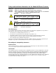
Safety and Installation Information for the Kodak i800 Series Scanners IMPORTANT: WARNING: Equipment shall be installed by qualified personnel . Dangerous voltage. Disconnect the main power before installation. WARNING: Before changing a lamp, always power down the scanner and let it cool a minimum of 10 minutes before proceeding (see Warning Labels below).
Taiwan Japan Class A This equipment is in the Class A category (Information Technology Equipment to be used in commercial and/or industrial areas) and conforms to the standards set by the Voluntary Control Council for Interference by Information Technology Equipment aimed at preventing radio interference in commercial and/or industrial areas. Consequently, when used in a residential area or in an adjacent area thereto, radio interference may be caused to radio and TV receivers, etc.
1 Introduction This User’s Guide provides information and operator procedures for the Kodak i800 Series Scanners. The information in this guide is for use with all of the i800 Series Scanners unless otherwise noted. Chapter 1, Introduction provides general information about the i800 Series Scanners including a product description, features and benefits, specifications, an overview of external components and user precautions.
Product description The Kodak i800 Series Scanners are ideal for operation with bi-tonal and/or color documents, documents with shaded backgrounds or foregrounds, and mixed document sets. These scanners offer a new, user interface and Kodak-patented technologies that produce high quality production images. Standard features The following features are standard on the Kodak i800 Series Scanners.
Four models of the Kodak i800 Series Scanners are available: Standard configurations • Kodak i810 Scanner (bi-tonal) provides bi-tonal scanning with throughput speeds up to 120 ppm • Kodak i820 Scanner provides both color and bi-tonal scanning simultaneously with throughput speeds up to 120 ppm • Kodak i830 Scanner (bi-tonal) provides bi-tonal scanning with throughput speeds up to 160 ppm • Kodak i840 Scanner provides both color and bi-tonal scanning simultaneously with throughput speeds up
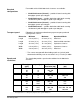
Scanner specifications Following are the dimensions and clearances for the Kodak i800 Series Scanners: Dimensions Height: 124 cm (49 in.) Width: 66 cm (26 in.) Depth: 127 cm (50 in.) Weight: 204 kg (450 lbs) including packaging 188 kg (414 lbs) without packaging Minimum clearances Normal Operation Maintenance Acoustic noise The table below provides the minimum clearances for normal operation and maintenance of the i800 Series Scanners: Front Rear Right Side Left Side Top N/A 4 in.
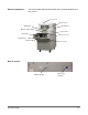
External components See the illustration below for the location of the external components of the scanner.
Environmental information and equipment disposal 1-6 • The Kodak i800 Series Scanners are designed to meet worldwide environmental requirements. • Guidelines are available for the disposal of consumable items that are replaced during maintenance or service; follow local regulations or contact Kodak locally for more information • The product packaging is recyclable. • Parts are designed for reuse or recycling.
2 Using the Scanner This chapter provides the following operational procedures: • Turning on the scanner • Document preparation • Adjusting the input tray, side guides and output tray • Scanning documents • Feeding long documents • Continuous and manual feeding Other functions, such as calibration, using the programmable keys, using multi-feed detection, setting the elevator level, etc. can be performed using the Operator Control Panel.
Document preparation Kodak scanners have been tested with a range of documents that represent the broad spectrum of document types found in the most common business applications. Optimal scanner performance is achieved when you scan documents within the recommended document specifications listed below. Scanning documents that are outside of these specifications may lead to undesirable results in terms of scanner reliability, image quality, and/or consumable life.
• For heavily damaged documents, a clear document protector can be used with the following limitations: Manual feeding is recommended when using a clear document protector. – The document in the clear document protector must be fed under both feed module tires. – Multi-feed detection must be disabled when manually feeding a document in a clear document protector. NOTE: When using a document protector, feed the fold of the document protector first rather than the open end.
Maximum document batch height for automatic feeding When feeding batched documents, the maximum height of the batched documents is 10.2 cm (4 in.), approximately 1000 sheets of 75g (20 lb.) paper. The elevator tray can be set to accommodate 25-, 250- 500-, 7501000-document stacks. Downward and upward curl documents The elevator tray can handle some amount of lead edge curl, but to ensure reliable feeding the curl should be at a minimum.
Adjusting the output tray Different paper types stack differently. The output tray can be set with either the front or the rear higher for best stacking. To angle the output tray so the back of the output tray is higher: 1. Lift the output tray up and pull it out of its current slot. 2. Reset it in the slot that matches the desired height.
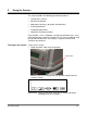
Scanning documents Before you scan documents, be sure the menu bar is displayed on the Operator Control Panel. Operator Control panel Documents must be fed under both feed module tires. For faster throughput, feed documents into the elevator tray in landscape orientation (longer side as the leading edge). To start scanning: 1. Enable the scanner from the host. 2. Place the documents to be fed in the elevator tray. 3. Press Start/Resume .
Loading long documents in the feeder The feeder accommodates documents up to 76.2 cm (30 in.) in length. To feed documents longer than 30.5 cm (12 inches): 1. Pull out the document extenders. Document extenders 2. Place the documents in the elevator tray. NOTE: Operator assistance is required when feeding documents longer than 43.2 cm (17 in.). Continuous and manual feeding Continuous feeding allows you to place additional batches of documents in the elevator tray (with operator assistance).
Feeding thick documents To feed thick documents: 1. Press and hold the gap release lever this provides more clearance to ease document feeding. Gap release lever 2. Push the envelope/thick document into the transport. If more than one document is to be scanned, feed them into the transport one at a time. 3. After the documents have been fed into the transport, release the gap release lever.
3 Operator Control Panel Functions There are a variety of functions available from the Operator Control Panel.
Enabling and disabling the scanner The five buttons at the bottom of the Control Panel correspond to the icons above the buttons To activate the icons, press the corresponding button. Icons Control panel buttons Enabling the scanner The scanner can only be enabled from the host computer. When the scanner is enabled, you can change the image address level, override the elevator setting and use the programmable keys.
Disabling the scanner The scanner can be disabled from the host computer or the scanner, if the end-of-job function is assigned to one of the programmable keys. When the scanner is disabled, you can display scanner information, lower the elevator tray, use the Diagnostics Settings menu, calibrate the scanner and jog the transport. Disabled scanner functions When the scanner is first powered on and disabled, the following icons will be displayed.
Navigating through the functions on the control panel menu The left and right arrows navigate along the top of the menu bar. In this example, the left and/or right arrow will rotate through the options of Exit, Diagnostics and Settings. The up and down arrows navigate through the menu selections. In this example, the up and/or down arrow will rotate through the options of Run self test, Run extended self test, Run count only, Run print test, Run patch test.
Accessing information The information icon will display information including the last image address, meter values, and scanner serial number. • Lowering the elevator tray Select this icon to display information. The level of the elevator tray can be set to accommodate various sizes of document batches. • Select this icon to lower the elevator tray to its lowest position. NOTE: This will temporarily override the setting, which is configured for elevator position from the Settings menu.
Performing a self-test or extended self-test You can perform a self-test or an extended self-test on the scanner. The self-test is the same test performed when the scanner is powered-up; the extended self-test is a more thorough test. To perform a self-test or extended self-test: 1. Select the Diagnostics Settings menu icon. 2. Use the right or left arrow to navigate to the Diagnostics function. 3. Use the down arrow to select Run self-test or Run extended selftest. 4. Select Return.
Performing a print test The print test checks to be sure the ink jets in the Document Printer are functioning properly. To perform a print test: 1. Select the Diagnostics Settings menu icon. 2. Use the right or left arrow to navigate to the Diagnostics function. 3. Use the down arrow to select Run print test. 4. Select Return. 5. Feed a blank(s) sheet of paper. 6. Press Start/Resume . 7. Press Stop/Pause. The documents in the output tray will display the results of the print test. 8.
Performing a patch test Use this test to verify that the Patch Reader is operational and that your patches are within specification. To perform a patch test: 1. Select the Diagnostics Settings menu icon. 2. Use the right or left arrow to navigate to the Diagnostics function. 3. Press the down arrow until Run Patch test is displayed on the Operator Control Panel. 4. Select Return. 5. Feed a document(s) with a patch(es). 6. Press Start/Resume .
Using the Settings menu The Menu icon displays the Diagnostics Settings menu. The following Settings functions are available: Changing the alarm volume • Changing the Alarm Volume • Changing the Display Contrast • Changing the SCSI ID • Changing the SCSI Termination • Setting the Elevator Position This setting allows you to adjust the volume of the alarm from 0 to 4. 1 = quietest; 4 = loudest; 0 = no sound. To set the alarm volume: 1. Select the Diagnostics Settings menu icon. 2.
Changing the display contrast This setting allows you to adjust the contrast of the display screen from 0 to 4. 0 = lightest, 4 = darkest. To change the display contrast: 1. Select the Diagnostics Settings menu icon. 2. Use the right or left arrow to navigate to the Settings function. 3. Use the down arrow to select Change Display Contrast. 4. Select Return. 5. Use the up and down arrows to select the desired contrast. 6. Select Return.
3. Use the down arrow to select Change SCSI ID. 4. Select Return. 5. Use the up and down arrows to select the desired SCSI ID number. 6. Select Return. 7. Turn the scanner off. Wait at least 10 seconds and turn the scanner back on again. 8. After the scanner has completed the self-test, reboot the host PC. Changing the SCSI termination This setting allows you to change the SCSI termination. Values are 0 (disabled) or 1 (enabled).
4. Select Return. 5. Use the up and down arrows to select the desired SCSI termination setting. 6. Select Return. 7. Turn the scanner off. Wait at least 10 seconds and turn the scanner back on again. The new termination setting will take effect. Setting the elevator tray position This setting allows you to select a position of the elevator tray. Elevator positions can be set to accommodate 25-, 250-, 500-, 750- or 1000documents (20-lb bond paper).
4. Select Return. 5. Use the down arrow to select the desired elevator position. 6. Select Return. The elevator position takes effect after the scanner is enabled. Calibrating the scanner Calibration optimizes your scanner to achieve the best image quality and feeding performance. The scanner can only be calibrated when it is disabled.
Jogging the transport The Jog button temporarily (4 seconds) turns on the transport to help clear a document jam. This function is only available when the scanner is disabled. The Jog button is intended to clear simple document jams. If documents are lodged in several locations within the scanner, use the procedures in Chapter 6, Troubleshooting/Messages. If a document jam occurs: • Programmable key assignments Select the Jog icon. There are three programmable keys on the Operator Control Panel.
4 Document Printer and Patch Reader This chapter provides instructions for using the Kodak Imagelink Document Printer 1 and the Patch Reader.
The Document Printer can print one line per document. The information printed by the Document Printer appears in a single column perpendicular to the leading edge of the document(s) as shown: Font size: two different character sizes, referred to as Large and Small, are available. The way the characters appear on the document will be dependent on the way your application is set up. Character orientation: information is printed on each document in either a Cine or Comic orientation.
Horizontal print position The horizontal print position is set using one of the 13 positions in the Document Printer well. Print position can be manually changed as required. To change the print position: 1. Open the swing out door. 2. Slide the green ink cartridge carrier out of its slot. 3. Move the ink cartridge to the desired position and insert it into the appropriate slot 4. Close the swing out door. NOTE: Printing automatically stops ½-inch (1.
Purging the ink cartridge Additional ink cartridges can be purchased from an office supply retailer nearest you. NOTES: • If the Document Printer will not be used for a period of time (24 hours or more), remove the Document Printer from the carrier and place it on its side until you are ready to use it. • Ink cartridges may be disposed of in accordance with local regulations. Before installing the ink cartridge, it must be purged.
4. Gently press the paper clip against the side of the ink bladder until a small bead of ink appears on the ink flow point on the ink cartridge. CAUTION: Do not puncture the ink bladder with the paper clip. 5. Remove the paper clip. 6. Allow the ink bead to absorb back into the ink cartridge. 7. Blot the excess ink with a lint-free tissue. CAUTION: Do not touch the ink flow point or you may cause improper ink flow.
3. Raise the locking bar if it is not already in the raised position and remove the empty ink cartridge. Locking bar 4. Insert a new, purged ink cartridge. 5. Lower the locking bar around the ink cartridge. 6. Slide the green ink cartridge carrier back into its slot. 7. Close the swing out door. IMPORTANT: 4-6 • Dispose of ink cartridges properly. Do not incinerate ink cartridges.
Replacing the ink blotter strips Ink blotter strips collect ink overflow. They should be replaced when there is a build-up of ink. Replacement blotter strips may be purchased through your supplier. See Chapter 5, Maintenance, for a list of available supplies. To replace the ink blotter strips: 1. Open the swing out door. 2. Lift the horizontal transport plate. 3. Remove the horizontal belt module. 4. Locate the blotter strips. You can replace one, some or all of the strips as necessary.
5. Grasp a blotter strip and carefully pull it off the transport. Discard the soiled strips. 6. Install the new blotter strip. Make sure that you align it in the transport channel before pressing the adhesive side into the channel. 7. Re-insert the horizontal belt module. 8. Lower the horizontal transport plate. 9. Close the swing out door.
Setting the printer position There are 13 possible positions for the printer. Make sure that the printer is in the correct position for your documents. 1. Open the swing out door. 2. Locate the printer positioning slots. 3. Determine which position is suitable for your printing needs. 4. Slide the green ink cartridge carrier out of its slot. 5. Slide the green ink cartridge carrier into the desired slot.
The Patch Reader The Patch Reader allows you to automatically increment the image address or initiate a special function. Patch sheets are placed in front of each document during document preparation or on the lead sheet of a document. There are 5 possible patch head positions. The patch head position can be easily changed. Recognition of all patch types will be returned in the image header. This is in addition to document level information.
Patch Types 2, 3 and T these patch types are used for image addressing. When the Patch Reader detects a patch, it automatically assigns a new image address to the new document. This eliminates the task of trying to determine where one document stops and the next starts when you are viewing electronic images. It provides a hierarchical document structure and offers an auto-batching alternative.
Setting the Patch Reader There are 5 patch locations available for patch reading. position 1. Set the documents in the elevator tray. 2. Open the swing out door. 3. Align the patch head with the location of the patch on the documents. 4. Close the swing out door. NOTE: If patches on the documents change location, repeat the procedure above for the new location.
5 Maintenance This chapter provides cleaning and replacement procedures for your scanner. For best scanner performance clean the areas outlined in this chapter every 8-hour shift, unless otherwise noted. Additional maintenance supplies can be ordering by calling DI Supply or through your Kodak Reseller. For a list of available supplies, see the section entitled, “Ordering Supplies” at the end of this chapter.
Cleaning the upper transport area Follow the steps below to clean the upper transport area: 1. Open the top cover. 2. Open the bi-fold door. 3. Grasp the end of the lower imaging guide and slowly pull it straight out. 4. Place the lower imaging guide on a clean surface. 5. Grasp the end of the upper imaging guide and slowly pull it straight out.
6. Place the upper imaging guide on a clean surface. NOTE: To avoid getting any debris (from the cleaning process) on the imaging guides, they will be reinstalled after the scanner is thoroughly cleaned. 7. Release the top turn baffle. Top turn baffle Exit transport plate 8. Vacuum the area. 9. Close the top turn baffle.
10. Lift and hold the exit transport plate and vacuum. 11. Lower the exit transport plate.
Cleaning the vertical transport area Follow the steps below to clean the vertical transport area: 1. Grasp the vertical transport plate and pull it down until it stops. 2. Slide the horizontal baffle plate out and vacuum inside the housing. Document sensors Black strip Horizontal baffle plate 3. With a soft cloth, wipe the document sensors and the black strip on the horizontal baffle plate. IMPORTANT: When vacuuming the scanner, be careful not to scratch the sensors. 4. Clean the document sensors. 5.
6. Vacuum the floor of the lower transport area. 7. Raise the vertical transport plate into its original position. 8. Turn the vertical transport plate handle and latch it into place. 9. Close the bi-fold door. 10. Close the top cover. Cleaning the transport area Follow the steps below to clean the transport area: 1. Open the swing out door.
2. Lift the roller cover and vacuum the sensors. Roller cover Sensors IMPORTANT: When vacuuming the scanner, be careful not to scratch the sensors. 3. Close the roller cover. 4. Lift the horizontal transport plate. 5. Remove the horizontal belt module.
6. Vacuum the floor of the horizontal transport area. 7. Wipe the upper and lower sensors with a lint-free cloth. 8. Reinstall the horizontal belt module. 9. Lower the horizontal transport plate.
Cleaning the printer and patch head Follow the steps below to clean the Document Printer 1 and Patch Reader head. Complete instructions for the Document Printer and Patch Reader can be found in Chapter 4. 1. Remove the Document Printer head and clean it with a dry, lint-free cloth. White clip 2. Reinstall the Document Printer head in the desired position. IMPORTANT: Be sure the cable is always kept in place by the white clip to prevent the cable from interfering with the imaging path. 3.
Cleaning the imaging guides Avoid getting fingerprints on the imaging guides during the cleaning procedure. 1. Open the bi-fold door. 2. Get the upper imaging guide that was set aside previously. Clean the upper imaging guide with a clean, soft, lint-free cloth slightly moistened with water. Lightly wipe both sides with a Staticide wipe. 3. Reinstall the upper imaging guide. Make sure the notched side is facing up and that the imaging guide is pushed in all the way and fully seated in its slot. 4.
Maintenance and replacement procedures This section provides procedures for replacing the following parts. Use the list below as a guideline for frequency of replacement. • Feed Module Tires and Separation Roller – tire life will vary depending upon paper types, environment and cleanliness. Nominal tire life will be approximately 250,000 documents; results will vary. Degradation of feeder performance, multiple feeds, stoppages, etc. indicate a need to change tires.
Replacing the feed module and feed module tires This section provides replacement procedures for the feed module and the feed module tires. Replacing the feed module To replace the feed module: 1. Open the swing out door. 2. Push the release lever to the right to release the feed module. 3. Remove the feed module. To install the new feed module: 4. Push the release lever to the right and reinsert the new feed module by aligning the pins and fitting it into position.
Replacing the feed module tires To replace the feed module tires: 1. Open the swing out door. 2. Remove the feed module. 3. With one hand, press the locking tabs (one on each side) while holding the bottom housing with the other hand, pull the upper housing up and away from the rollers. 4. Remove one core assembly. 5. Replace each tire by sliding the tire off the core.
6. Install each new tire by gently stretching it over the core. IMPORTANT: Do not overstretch the tire; it may tear. 7. Replace the core assembly in the feed module. 8. Repeat Steps 4 through 7 for the other core assembly. 9. Align the tabs on the upper housing with the slots on the lower housing. 10. Press the upper and lower housings together until they snap into place. 11. Insert the feed module by aligning the pins and fitting it into position. Verify that it is securely in place. 12.
Separation roller and tires This section provides procedures for changing the separation roller and tires. Replacing the separation To replace the separation roller: roller 1. Open the swing out door. 2. Lift the roller cover. 3. Pull the separation pad holder forward and remove the separation roller. To install the new separation roller: 4. Pull the separation pad holder forward and put the new separation roller in place. NOTE: Be sure to line up the slots on the separation roller with the holders. 5.
Replacing the separation To replace the separation roller tires: roller tires 1. Remove the separation roller as previously directed. 2. Replace each tire by sliding the tire off the core. 3. Install each new tire by gently stretching it over the core. IMPORTANT: Do not overstretch the tire; it may tear. 4. Reinstall the separation roller as previously directed. Changing the separation pad Change the pre-separation pad when the frequency of double-fed documents increases. 1. Open the swing out door. 2.
Cleaning the feed module tires and separation roller tires The cleaning procedures below should be performed daily. More frequent cleaning may be necessary depending on throughput and document type. Daily cleaning of the feed module tires and separation roller tires prevent ink, toner, dust and paper contaminates from collecting on the rollers, which help documents to separate properly when feeding. 1. Open the swing out door. 2. Remove the feed module. 3. Lift the roller cover. 4.
2. Grasp the green handle of the lamp connector. 3. Slightly raise the edge of the black holder and remove the lamp connector. 4. Grasp the end of the lamp and slowly pull the lamp straight out. NOTE: Like most fluorescent lamps, these lamps contain a small amount of mercury and should be disposed of in accordance with local regulations.
5. Position the new lamp in the lamp holder. IMPORTANT: Make sure that the clear surface of the lamp is positioned facing the imaging guides. (NOTE: The imaging guides are not installed in the illustration above.) Replace one lamp at a time to ensure the correct connector is inserted with each lamp; otherwise lamps may not function properly. 6. Push firmly on the end of the lamp to seat the lamp into the socket on the other end. 7.
Replacing the imaging guides To replace the imaging guides: 1. Open the bi-fold door. 2. Remove the imaging guides. 3. Slide a new upper imaging guide in place. Make sure the notched side is facing up and that the imaging guide is pushed in all the way and fully seated in its slot. 4. Slide a new lower imaging guide in place. Make sure the notched side is facing up and that the imaging guide is pushed in all the way and fully seated in its slot. 5. Close the bi-fold door.
Customizing the side guides for selfcentering feeding A spacer is installed in the output tray, which allows the side guides to move independently. If you want the side guides to move together (selfcentering) you can install the geared spacer that is included with the scanner. To change the side guides for self-centering feeding, follow the procedures below. Tools needed: Phillips Head Screwdriver 1. Pull the output tray forward and remove it. 2.
3. Use the screwdriver to release the center screw. 4. Remove the spacer and washer. 5. Take the geared spacer and place it over the post, being sure to align the teeth on the racks. 6. Add the washer and screw and gently tighten until the spacer and washer are firm. NOTE: Do not overtighten.
7. Turn the tray right-side up, reinstall the end stop and verify the guides move freely. 8. Replace the output tray. Changing the output tray side guides The output tray comes with a set of short and tall side guides, which can be easily changed. Tools needed: Phillips Head Screwdriver 1. Remove the output tray. 2. Remove the end stop. 3. Turn the tray upside down. 4. Use the screwdriver to release the screws. 5. Turn the tray over and remove the short (or tall) side guides.
6. Take one tall (or short) side guide, position the guide and hold it in place. 7. Continue to hold the side guide in place and turn the output tray over. Put the screws in place and tighten. 8. When finished with the first side guide, turn the tray back over and attach the other side guide; follow Steps 6 and 7. 9. Replace the end stop (short or tall as required). 10. Replace the output tray.
Ordering supplies The following supplies are available to properly maintain your system. Order them in the United States by calling DI Supply at 1-888-247-1234 or contact your local Kodak Reseller. Outside of the United States, contact your local Kodak dealer.
6 Troubleshooting/Messages This chapter provides the following: • • • • Clearing the document path procedures for clearing the document path, information regarding document printing problems, a message listing and the actions you can take to clear the message, a problem solving chart and when to call Service. In the rare instance when a document becomes lodged in the transport, the scanner stops running and a message appears on the Operator Control Panel. The scanner will become disabled.
If there are still lodged documents: 3. Open the swing out door. 4. Lift the horizontal transport plate and remove any documents. 5. Close the horizontal transport plate. 6. Close the swing out door. Top cover access 7. Open the top cover. 8. Open the exit transport plate and remove any lodged documents. 9. Close the exit transport plate.
10. Open the upper turn roller and remove any lodged documents. 11. Close the upper turn roller. 12. Close the top cover. Clearing the document path – bi-fold door access Occasionally documents can become lodged in the imaging guide area. If this is the case: 13. Open the bi-fold door. 14. Remove the imaging guides. 15. Lower the vertical transport plate and remove any lodged documents.
16. Slide out the horizontal baffle plate and remove any lodged documents. 17. Slide the horizontal baffle plate back into position and close the vertical transport plate. NOTE: Be sure the vertical transport plate is securely locked into position. 18. Reinstall the imaging guides. 19. Close the bi-fold door. 20. Re-enable the scanner from the host.
Message Listing Following is a list of messages and corrective actions you can take if one of the following messages appears on the Operator Control Panel. Most corrective actions can be found in this User’s Guide; appropriate chapters are referenced. If one of the following messages appears, take the following action: • • • Determine whether or not the error can be addressed from the host system.
Message Description Message Action Check document preparation The documents are not prepared properly for scanning. See Chapter 2, Using the Scanner, for procedures on how to properly prepare your documents. The documents are too close together as they enter the scanner. Change the separation rollers and pre-separation pad. See Chapter 5, Maintenance for the procedure for changing the separation roller and pre-separation pad. The cropping parameters are set improperly.
Message Description Message Action Feeder self test failed The self-test of the paper feeder failed. Perform a controlled power-down sequence on the scanner. If the problem persists, call Service. Message Action Front image cal unsuccessful The imaging calibration for the front camera was unsuccessful. Clean the imaging guides and retry calibration. See Chapter 5, Maintenance, “Cleaning the imaging guides” for cleaning procedures.
Message Description Message Action Mechanical cal unsuccessful The mechanical calibration was unsuccessful. Be sure the correct calibration target was used and that the arrows on the target were feed into the transport first. See Chapter 3, Operator Control Panel Functions, “Calibration” for more information. Message Action Motor self test failed The self-test of the paper transport motor failed. Perform a controlled power-down sequence on the scanner. If the problem persists, call Service.
Message Description Message Action Print head not present An attempt was made to use the Document Printer and no print head is installed. Be sure the cables are properly connected to the print head and printer board. Be sure the print cartridge is installed in the print head assembly. See Chapter 4, Document Printer and Patch Reader for procedures. Message Action Rear image cal unsuccessful The imaging calibration for the rear camera was unsuccessful. Clean the imaging guides and retry calibration.
Message Description Message Action Unable to enable Check to be sure all doors are closed. If all the doors are closed, perform a controlled power-down sequence. If the error persists, call Service. Message Action Unable to execute command You have tried to perform a function that is not permitted in the current state of the scanner or with invalid parameters. For example, you attempted to run the scanner when it is not enabled; or if you attempted to run the scanner when you have a paper jam.
Problem solving chart Use the chart below as a guide to check possible solutions to problems you may encounter when using the Kodak i800 Series Scanners. Problem Possible Solutions Scanner does not power on (Control Panel is not illuminated) Make sure that: • • • The scanner will not scan/feed documents Make sure that: • • • • • • • Image quality is poor or has decreased the power cord is plugged securely into the receptacle in the back of the scanner.
Problem Possible Solutions Calibration has failed Make sure that: • • • • • • the lamps have been on at least 10 minutes. you are using the proper calibration target and it is oriented correctly. the imaging guides are clean (see Chapter 5, Maintenance, “Cleaning the imaging guides”). the transport area is clear of obstructions. the sensors are clean. the lamp timeout is set for greater than 10 minutes. Try calibration again.
Problem Possible Solutions The output tray cannot be adjusted in or out Make sure the output tray is installed properly. Roller marks appear on documents after scanning Clean the feed module rollers, separation rollers and transport rollers (see Chapter 5, Maintenance).
Problem Possible Solutions White lines appear at the top of the document then stop as the document is imaged. Clean the black backer strip on the horizontal baffle plate. For procedures see Chapter 5, “Cleaning the vertical transport area”.
EASTMAN KODAK COMPANY Commercial Imaging Rochester, New York 14650 Kodak is a trademark of Eastman Kodak Company. Printed on recycled paper. A-61169 7/03 CAT No. ©Eastman Kodak Company, 2003 Printed in U.S.A.