SRP 30 LASER PRINTER OPERATOR'S GUIDE
Operator’s Guide KODAK PROFESSIONAL SRP 30 Laser Printer P/N 6B7503 December 2002
© Eastman Kodak Company, 2002 All rights reserved. Contents of this publication may not be reproduced in any form without permission from Eastman Kodak Company.
Table of Contents Regulatory and Safety Information............................................................. iii Regulatory Compliance .................................................................................. iv Cautionary Symbols and Labels..................................................................... iv Laser Compliance and Safety ......................................................................... v Safety Precautions ..............................................................
Operator’s Guide Chapter 6 Production................................................................................. 6-1 Preparing the Equipment for Different Orders ............................................. 6-3 APS Film ...................................................................................................... 6-9 Order Handling........................................................................................... 6-10 Print Modes Overview..............................................
Regulatory and Safety Information Contents Regulatory Compliance ............................................................................................ iv EMC Compliance................................................................................................. iv CE Compliance.................................................................................................... iv Cautionary Symbols and Labels..............................................................................
Operator’s Guide Regulatory Compliance EMC Compliance NOTE: This equipment has been tested and found to comply with the limits for a Class A digital device, pursuant to Part 15 of the FCC rules. These limits are designed to provide reasonable protection against harmful interference when the equipment is operated in a commercial environment.
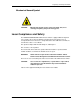
Regulatory and Safety Information Mechanical Hazard Symbol CAUTION: Moving parts. Avoid contact. Keep your hands, hair, loose clothing, and jewelry away from moving parts. Laser Compliance and Safety The KODAK PROFESSIONAL SRP 30 Laser Printer is equipped with an Argon Ion Laser of Class 3B. To prevent damage caused by the laser beam, the laser is encapsulated. Because the laser is encapsulated, the entire SRP 30 Laser Printer is classified as a Class 1 Laser Device.
Operator’s Guide Certification Labels A B C Non-interlocked Panel Label D Aperture Label E vi KODAK PROFESSIONAL SRP 30 Laser Printer
Regulatory and Safety Information Laser Source Label F Locations of Laser Safety Labels B C (side) A E F D KODAK PROFESSIONAL SRP 30 Laser Printer vii
Operator’s Guide Safety Precautions Legal Notice The SRP 30 Laser Printer is designed for operation in conformance with all local safety regulations. Follow all safety regulations, warnings, and instructions on machine labels. Failure to observe these regulations may result in personal injury or damage to the equipment and working area. The manufacturer and service provider will not assume any responsibility for accidents and damage resulting from incorrect operation.
Regulatory and Safety Information Handling of Processing Chemicals Disposal of Chemicals and Containers Effluent Management IMPORTANT: Regulations and requirements regarding the proper disposal of photographic processing effluents vary by region and by locality.
Operator’s Guide Safety Precautions for the Handling of Chemicals WARNING: Follow these guidelines for the safe handling of chemicals in the equipment working area. General Guidelines • Be sure that all persons operating the equipment have a complete set of instructions for the handling of dangerous substances. • Be sure that all persons operating the equipment have training on the handling of dangerous substances at least once a year. • Check for sufficient room ventilation in the working area.
Regulatory and Safety Information Warranty Information The following warranty information pertains to equipment that is installed in the United States only. For equipment installed in countries other than the United States, the terms and conditions of the new equipment warranty are provided by the Kodak company in the country in which the sale is finalized, or by a Kodak-appointed distributor in countries where Kodak does not have direct sales representation.
Operator’s Guide Limitations Warranty service is limited to areas within Kodak’s established marketing centers in the contiguous United States, the island of Oahu in Hawaii, and some areas of Alaska. This warranty does not cover circumstances beyond Kodak’s control; it does not cover service or parts for any attachments, accessories, or alterations not marketed by Kodak, nor to correct problems resulting from their use.
Chapter 1 Introduction Contents Using the Documentation ....................................................................................... 1-2 Structure ............................................................................................................1-2 Text Styles.........................................................................................................1-2 Notices...............................................................................................................
Operator’s Guide Using the Documentation Structure This Operator’s Guide contains information about: • Safety precautions • Machine settings • Print configurations • Production • Maintenance Text Styles In this guide, bold print indicates screen or button designations. Examples: “Touch OK to validate the displayed text and close the Input screen.” “Touch Reorder to process reorders.” Italic print indicates cross-references. Example: “Also see Safety Precautions on the following page.
Introduction Safety Precautions See the Regulatory and Safety Information in the front of this guide for details about: • Electrical precautions • Operation of the equipment • Disposal of the equipment • Handling and storage of processing chemicals • Laser safety Follow all safety regulations, warnings, and instructions that are on equipment labels and in the guide.
Operator’s Guide 1-4 KODAK PROFESSIONAL SRP 30 Laser Printer
Chapter 2 Overview Contents General Description ................................................................................................ 2-3 Product Description ...........................................................................................2-5 Image Editing.....................................................................................................2-6 Functional Procedure.........................................................................................
Operator’s Guide Screen Structure ................................................................................................... 2-21 Information Area.............................................................................................. 2-22 Touch-sensitive Buttons.................................................................................. 2-24 Drop-down Menus...................................................................................... 2-25 Pop-up Windows .......................
Overview General Description The SRP 30 Laser Printer contains four major components: 1. Main computer (separate, but integrated into the scanner housing) – controls the general work process and generates the image exposure data. The monitor for the operation of the system is connected to the main computer. 2. Scanner – digitizes frames and slides and determines corrections and exposure values. 3.
Operator’s Guide 1 Exposure unit with laser fiber and laser module 10 Order sorter 2 Touch-screen monitor 11 Main breaker, ground fault interrupter (GFI) switch 3 Film feeder with a cleaning brush 12 Drain valves for the chemical overflow 4 Film mask for the scanner 13 Right-hand paper magazine 5a Printing lamp 14 Lane distributor 5b Filter wheel 15 Lens and CCD 6 Film take-up 16 Transport unit 7 Wet section with racks, crossovers, and chemical filters 17 Film collecting box 8 Built-in dens
Overview Product Description The SRP 30 Laser Printer provides convenient and quick printing of: • Black-and-white and color negative films • Color slides (frames) • Digital images The digital image files are transferred to the SRP 30 Laser Printer by: • Data carriers − Diskette − ZIP disk − CD-ROM or Smart Media card (by way of PCMCIA adapter) • Network (workstation) NOTE: It is your responsibility to provide for a network and/or a workstation and to provide for its connection.
Operator’s Guide Image Editing The SRP 30 Laser Printer offers a wide variety of image editing options: • Color and density corrections • Cropping • Image enhancement − area and detail contrast − sharpness − saturation • Special features − colored texts − borders These modifications are calculated on the image processing board. The image in the display refreshes immediately.
Overview Functional Procedure The SRP 30 Laser Printer performs the following functions to process print orders. • Prescans and scans the image • Cuts the paper • Transports the paper • Edits the image, if necessary • Exposes the image • Distributes the paper to the appropriate lane to the processor • Processes the image • Deposits the prints in the sorter These steps are described in the next section, Film Advance and Paper Transport.
Operator’s Guide Main Computer The main computer—by way of the image-processing card—processes the digitized image data, the prescan data, and your correction and image editing data. The computer converts the data to an exposable image and sends it to the printer. Printer The printer transports the cut paper (1) to the print engine (2), exposes the paper to the laser beam, and advances it through the transport unit (3) up to the lane distributor (4). The back print (5) is applied in the lane distributor.
Overview Paper Processor The exposed paper advances through the processing solutions (1), which include the developer, bleach-fix, and stabilizer. The paper then advances through the dryer (2). Sorter After drying, the prints exit from the print chute (1) into the sorter (2) where they are sorted by orders and stacked in trays. • If a print order exceeds the capacity of one tray (a maximum of 43 prints), the sorter automatically switches to the next tray without terminating the print order.
Operator’s Guide Densitometer The built-in densitometer (1) above the dryer automatically measures the test print.
Overview Starting the Equipment IMPORTANT: Before starting the equipment, insert the loaded paper magazines. Any film mask may be in the equipment when it is started.
Operator’s Guide Manual Startup 1. Turn on the main circuit breaker (1). 2. Press the ON button (2). The ground fault interrupter (GFI) switch below the main circuit breaker always remains on.
Overview System Startup Status After automatic or manual startup, the equipment heats the solutions and the dryer to nominal temperatures. During this phase, the monitor displays: • The progress of the heating process • The remaining time until the equipment is ready to operate • Any error messages • The Stop button to shut down the equipment correctly any time during the startup process The equipment is ready for operation after the solutions and the dryer have reached nominal temperatures.
Operator’s Guide Start Screen After you log in, the menu bar with the five main menus appears. • Print mode offers all functions for image editing and printing. (See Production, Chapter 6.) • Settings lets you create print configurations, enter system-specific parameters, and define order prices. (See Settings, Chapter 4.) • Test lets you test the equipment prior to the production start and during production. (See Tests, Chapter 5.
Overview End of Work Changing Users To change users, you must first log out. 1. Select End of work on the menu bar. 2. Touch Change user. 3. Touch Logout.
Operator’s Guide Work can only continue if you follow these steps to log in. 1. Select the name of the next user. 2. Enter the password (four numbers). 3. Touch Login. If a different language is allocated to the new user in the system setup, all text is displayed in that language.
Overview Shutting Down The two methods of shutting down the SRP 30 Laser Printer are: • Automatically, by way of the integrated timer – the preferred procedure • Manually, by selecting End of work on the menu bar – the alternate procedure Automatic Shutdown The equipment shuts down automatically if you enter no input within a preset time period after system start. To define the preset time period, see Defining Times for Startup, Shutdown, and Sleep Mode in Chapter 4.
Operator’s Guide 3. Change the start information in the display, if necessary: • Change Timer Change the date and time for the next startup in the opening screen. • Next Login Select the user for the next startup. NOTE: Changes of the start time and the user are only valid until the next startup. Permanent changes are only possible using the equipment settings. 4. Perform the daily maintenance procedures. (See Daily Maintenance in Chapter 8.) 5. Reply to all checks, if any: a.
Overview Description of the Operating Controls Buttons and Lamp on the Main Computer There are two buttons and one lamp on the main computer: • ON button (1) If the system is shut down by End of work – Shutdown, it remains in the timer mode until the next automatic startup. If you must operate the system before the next automatic startup time, press the ON button. The system will then start up. You can also press the ON button to initiate a reset.
Operator’s Guide Touch-screen Monitor The operation of the equipment is menu-driven by a touch-screen monitor. Activate the functions by touching the touch-sensitive buttons on the screen. Specifications: • 15-inch LCD screen • SVGA resolution 1024 x 768 pixels • Screen-refresh frequency > 75 Hz For more information, see Screen Structure on Page 2-21, Touch-sensitive Buttons on Page 2-24, and Menu Overview on Page 2-31.
Overview Screen Structure 9 NOTE: This operator’s guide refers to the touch-sensitive fields of the touch-screen monitor as “buttons.” The screen is divided into several areas: 1 Information area with 2 fixed buttons (i, ?, Stop) and 3 status line 4 Active screen with 5 buttons and 6 a popup window, if available (not shown in the above example) 7 Menu bar with five main menus The areas 1, 2, 3 and 7 are always displayed. However, the menu bar (7) cannot always be used.
Operator’s Guide Information Area The Information area includes the fixed buttons (i, ?, and Stop) and the status line. Because the fixed buttons are always accessible, you can open the Info and Help screens at any time. For more information, see Info and Help on Page 2-40. The fixed buttons are described below. i Status information ? Context-related help for all screens and error messages Stop If the system does not respond to operator entries, you can use this button to initialize a software reset.
Overview The display in the status line includes: • Information, warnings, and requests • Error messages The messages in the status line require different actions: • Some messages let you continue working without confirmation or action. • Some messages can be ignored several times until the system forces you to act. • Error messages must be resolved before work can continue. All error messages are saved. You can view a list of the messages by touching i, then Error list.
Operator’s Guide Touch-sensitive Buttons NOTE: Only one screen is active. It is not possible to open several screens at the same time. The buttons in areas of the screen other than the Information line (i, ?, and Stop) change with the functions of the associated menu.
Overview Drop-down Menus When you touch a button that lets you make a selection, a drop-down menu opens. If there are more entries than the display can show, arrow keys appear for scrolling. For example, when you select a paper-width configuration, a drop-down menu appears with all configurations that you can select for the inserted paper width. 1. Select the desired configuration from the list. 2. Touch OK.
Operator’s Guide Pop-up Windows Pop-up windows open on the active screen if you must make a confirmation or perform an action. • A Reset pop-up appears when you press the Stop button on the main computer (or the Stop button on the touch screen) when a suspected film jam occurs. The film is moved out and the order is interrupted. To prevent subsequent paper jams, empty the paper transport in the printer before you press Yes to initiate a system reset.
Overview • A Warning pop-up appears if a risk of data loss occurs. • An Info pop-up appears to provide additional status information. • A Query pop-up appears for you to avoid potential problems.
Operator’s Guide Input Screen When you must enter text, numbers, or special characters, the Input screen opens. • The image of a keyboard includes national special characters in accordance with the selected keyboard allocation. (For the selection of the keyboard allocation, see User Interface in Chapter 4.) Touch a button to select the corresponding character. • Typed characters appear in the blue field and in the button above the image of the keyboard.
Overview Numeric Keypad Use the numeric keypad in the display to enter the desired number and touch OK to confirm.
Operator’s Guide Reorder Keyboard The Reorder keyboard on the touch screen lets you edit Reorder lists.
Overview desired, 0 must be entered. Menu Bar The main menus are always accessible, except when either a pop-up window is open or the Help screen is open. Menu buttons that appear gray indicate that the function is not available. The structure of the menus is described in the next subsection, Menu Overview.
Operator’s Guide Print Mode Menu Image editing: Crop files Position text Enter border positioning 2-32 KODAK PROFESSIONAL SRP 30 Laser Printer
Overview Settings Menu without Equipment Settings Machine Machine Indexprint KODAK PROFESSIONAL SRP 30 Laser Printer Indexprint 2-33
Operator’s Guide Settings Menu with Equipment Settings ar Machine Machine balance Remote 2-34 KODAK PROFESSIONAL SRP 30 Laser Printer
Overview Test Menu Piko KODAK PROFESSIONAL SRP 30 Laser Printer 2-35
Operator’s Guide Pricing + Statistics Menu Statistics 2-36 KODAK PROFESSIONAL SRP 30 Laser Printer
Overview End of Work Menu Login Timer KODAK PROFESSIONAL SRP 30 Laser Printer 2-37
Operator’s Guide Status Information and Help Menus Film drive Info 2-38 KODAK PROFESSIONAL SRP 30 Laser Printer
Overview Other Screens These screens are accessible at any time. They are displayed when: • Configurations can be modified on demand with the Display Config.
Operator’s Guide Info and Help Information is available in every screen by pressing i in the Info field. The Info screen displays the operating hours of the scanner lamp and the laser. You can reset the counter for the operating hours of the scanner lamp in the Test / Maintenance menu. For all other information, a separate screen opens. • To open the Film drive Info, Printer Info, and Paper Processor Info screens, touch the module in the illustration that appears on the touch-screen.
Overview NOTE: When an error occurs, the module concerned appears in red. Touch the button on the module to localize the error more precisely. The defective component is shown below (in red).
Operator’s Guide Film Drive Info The Film drive Info screen provides a graphic representation of the film advance. If an error occurs, the corresponding component of the film advance appears in red. To return to the Info screen, touch Back.
Overview Info Printer Info Printer is a graphic representation of the paper transport. This screen shows the width, surface, and residual length for each paper magazine. If an error occurs, the corresponding component of the printer appears in red. To return to the Info screen, touch Back.
Operator’s Guide Info Paper Processor Info Paper Processor is a graphic representation of the solutions and the dryer. This screen also displays: • Number of prints moving through the paper processor • Order numbers of the orders in the paper processor • Time remaining until the last print will exit • Reference and actual temperatures of the solutions and the dryer If an error occurs, the corresponding component of the paper processor appears in red. To return to the Info screen, touch Back.
Overview Info Order The Info Order screen displays the number of orders that are not yet processed: • APS reorders • Network orders • Orders stored for file prints (Backup) To return to the Info screen, touch Back.
Operator’s Guide Version Info The Version Info screen displays: • Current versions of the installed software and firmware • Serial number of the hardware • License ID of the equipment To return to the Info screen, touch Back.
Overview Error List All error messages shown in the status line are saved. To view the error list, touch i, then Error list. The Error list screen shows the date, time, type, and text for each error. • Disable Display all errors if the error list only shows the errors encountered since the last start or reset. • If the error message is not displayed completely in the error list, touch the message to display the complete text below the error list.
Operator’s Guide Help You can access Help from every screen that has a ? in the information area. (See Screen Structure on Page 2-21.) NOTE: For operations requiring significant computing time, the Help window does not display immediately. A pop-up window opens with the following options: • Waiting • Cancel Help text appears for the screen in which you touched ?. The display includes links to the Help texts.
Chapter 3 Chemicals Contents Preparation of Chemicals ....................................................................................... 3-3 Rinsing the Tanks..............................................................................................3-4 Mixing the Tank Solutions .................................................................................3-5 Stabilizer.......................................................................................................3-6 Bleach-Fix............
Operator’s Guide 3-2 KODAK PROFESSIONAL SRP 30 Laser Printer
Chemicals Preparation of Chemicals WARNING: A risk of injury is possible if the cover of the wet section is unlocked (when PUSH is pressed unintentionally). • When opening the cover: Check that the cover lock fully engages in the vertical position. • When closing the cover: Support the cover with one hand. Press the unlocking lever (PUSH), and close the cover. A water temperature of approximately 30°C (86°F) is recommended for the preparation of the individual tank fillings.
Operator’s Guide CAUTION: To prevent contamination of the chemicals, always fill the tanks in the following order: SB Ö BX Ö CD After each preparation of a solution, thoroughly rinse the containers used for the preparation first with cold water, then with hot water. Rinsing the Tanks 1. Open the wet section cover. 2. Fill the replenisher tank with water until the lower level sensors are covered to avoid the request for the connection of an EKTACOLOR Processing Cartridge. 3.
Chemicals Mixing the Tank Solutions The instructions assume that you are mixing the fresh-tank solutions directly in the processor tank. WARNING: Use cold water when you mix solutions to prevent you from unnecessary exposure to fumes that can be released at higher temperatures. Handle all chemicals carefully. When you mix solutions, wear goggles or a face shield, a protective rubber apron, and protective gloves made with either neoprene or nitrile rubber.
Operator’s Guide Stabilizer 1. Add 10.3 L of water to the first tank. 2. Add one-half the contents (approximately 72 mL) of one bottle of stabilizer concentrate (labeled SB). 3. Repeat Steps 1 and 2 for each of the three remaining stabilizer tanks. The total volume for each tank is 11 L. Bleach-Fix You can mix the working bleach-fix tank directly from the two-part concentrates. Use two EKTACOLOR Processing Cartridge 75 units to supply the two bottles of each of the two concentrate solutions.
Chemicals Installing the Racks and Bringing the Tank Solutions to Temperature When you fill the tanks with the new mixes, they appear only partially filled. When you reinstall the racks in the tanks, the racks displace more solution volume to fill the tanks. 1. Install each rack by slowly lowering it into the tank; the rack displaces additional volume to fill the tank and partially mix the solution. 2. When you have reinstalled all the racks, verify that all tanks are filled with solution. 3.
Operator’s Guide 4. Put the EKTACOLOR Processing Cartridge in the docking station with the sticker facing up. The preparation of the replenishers starts as soon as the docking station is closed. During this procedure, the door is locked mechanically and the LED on the left side of the docking station illuminates steadily. IMPORTANT: To reduce oxidation, a cartridge should always be in the docking station. After the LED is turned off, the cartridge can be removed and replaced by a full one.
Chapter 4 Settings Contents From the Order Receipt to the Finished Print ...................................................... 4-3 Administrator .....................................................................................................4-3 Operator ............................................................................................................4-4 Settings.....................................................................................................................
Operator’s Guide Production Balance – Digital........................................................................... 4-43 Digital Order Settings...................................................................................... 4-45 Other Settings ................................................................................................. 4-47 Print Configurations .............................................................................................
Settings From the Order Receipt to the Finished Print Administrator Administrator actions Initiated using the following buttons Settings for the automatic Startup by the timer: start times, first user, calendar with off-days and company holidays Settings Machine settings Startup Configuration settings: Used as a basis for the Print configuration.
Operator’s Guide Operator Operator actions Operator logon Initiated using the following buttons or actions End of work Change user 1. Select a name for the operator. 2. Enter the Password. 3. Touch Login. Preparing the machine for the order 1. Mount a suitable mirror box and film mask. 2. Prepare paper magazines (insert paper, code magazine) and mount them Testing the paper and the machine: Be sure to use MBL (Master Balance) paper for the first PBL (Paper Balance).
Settings Settings You can only modify settings when the film drive, the printer, and the paper processor are empty: • No film in the film mask • No paper in the printer • No paper in the paper processor The Settings menu is disabled as long as film or paper is advancing through the system. To open the Setting screen, touch Settings on the menu bar. The following options are available: • Print configurations For creating print configurations for production, with all associated subconfigurations.
Operator’s Guide Entering Names If a name is required (for new configurations, for example), the Input screen opens automatically. Configuration names have a maximum length of 30 characters. Special characters are permitted, except for quotation marks. 1. Touch the appropriate characters on the keyboard. Characters appear in the blue field above the keyboard as you enter them. They also appear in the button next to the blue field.
Settings Entering Numbers If a number is required (for the numeric user password, for example) the numeric keypad opens automatically. 1. Touch the appropriate numbers on the keypad. The numbers appear in the blue field above the keypad as you enter them. 2. Touch OK to confirm.
Operator’s Guide Machine Settings To open, touch: • Settings • Machine settings The settings are divided into two sections: Configuration and Machine. This division has an effect on Saving and Loading. The configuration settings are saved and loaded together with the print configurations. Configuration: • Surface and Paper settings Set the switches according to the paper magazine coding for the surfaces (5 and 6) and the paper widths (1–4). (See Coding the Paper Magazine on Page 4-13.
Settings • Production balance Color/density corrections, surface and detail contrast, sharpness, saturation, and TFS logic (color, density selector) • Network orders (Digital orders) Settings to receive and send remote orders (file print / Autosave) and network orders • Install Software Updating the system software and installation of optional software components (such as Pricing) • Set date/time • Other Entry of lab name/ID for the back print, settings for the automatic end of order and automatic order nu
Operator’s Guide Surface XYZ 3. Touch PFDF surface and select from a list of standard PFDF surfaces such as Matte, Glossy, or Lustre. 4. Touch Switches 5 and 6 to define the name of the paper surface. (See Coding the Paper Magazine on Page 4-13). 5. Touch Save as if you are creating a new configuration, and enter a name. Touch Save to save changes to an existing configuration. Touch Cancel to return to the previous screen without saving.
Settings Defining Paper Settings 1. Touch: • Settings • Machine settings • Paper settings 2. Touch New or select an existing configuration and touch Edit.
Operator’s Guide 3. Touch Switches 1 to 4 to define the paper width. (See Coding the Paper Magazine on Page 4-13.) 4. Touch Save as if you are creating a new configuration, and enter a name. Touch Save to save changes to an existing configuration. Touch Cancel to return to the previous screen without saving. The total number of paper widths usable without modification is 16. Up to four different surfaces can be used in the same way for all widths.
Settings Coding the Paper Magazine White slide tabs located on the paper magazine let you code the width (1–4) and surface (5 and 6) of the paper in use. Whenever you change paper, set the slide tabs accordingly. The meaning of the coding is described below. Slide tab closed (corresponds to switch setting Slide tab open (corresponds to switch setting on the SRP 30 screen) on the SRP 30 screen) Width Indicators Paper Width Surface Indicators 1 2 3 4 5 6 3.25 inch (82 mm) 3.
Operator’s Guide Defining the Cut Lengths 1. Touch: • Settings • Machine settings • Cut length 2. Touch New cut length or Delete cut length to update the list of created cut lengths. The range is 82–305 mm (3.2–12.0 in.). Paper width Minimum cut length <121 mm (4.75 in.) 121 mm (4.75 in.) 121–178 mm (4.75–7.00 in.) 82 mm (3.25 in.) >178 mm (7.00 in.) 121 mm (4.75 in.) Comments Images are rotated before printing 3. Touch Save.
Settings User Interface 1. Touch: • Settings • Machine settings • User interface 2. Select the data for the user-specific settings: • Language German, English, French, Italian, Spanish, etc. • Keyboard for the input screen on the touch screen • Preview freq. The frequency with which the Preview images advance in the Autoprint, Reorder, and File Print modes. The fastest possible frequency is preset (3 seconds).
Operator’s Guide User Administrator: Defining Users and User Rights The User interface settings are needed for user-specific functions and must be in place before users can logon to the system. You can define any number of users, but two user types are required: • Administrator – with user rights for all functions, except Service. • Service – with unlimited rights for all functions. 1. Touch: • Settings • Machine settings • User manager 2. Touch New or select an existing user and touch Edit.
Settings NOTE: Changes to these settings become effective only after the next user login. tom 3. Define or change the password. (Passwords are a maximum of four digits.) a. For a new user, touch Password. For an existing user: • Touch Old Password. • Enter the existing password and touch OK. • Touch Password. b. Enter the new password and touch OK. c. Touch Repeat and enter the new password again for verification. 4. Enable or disable Language, Keyboard, Preview freq., and Beep Touch.
Operator’s Guide User Profiles Rights Print modes Description Autoprint First-time (new) orders Reorder Reorders File print Image files of an order (loaded from data media) Preview Autoprint, Reorder, File print with Preview Manual positioning Originals that cannot be handled in Autoprint or Reorder mode: Single frames, strips without space detection Network orders File print (Remote), Autosave (Remote), Network orders from a workstation Configurations Create or modify order configurations,
Settings Defining Times for Startup, Shutdown, and Sleep Mode 1. Touch: • Settings • Machine settings • Startup 2. Touch the buttons under the Start and Sleep mode/shutdown headings to define the times for each day. Set to Off for off days. • For the automatic start times, allow approximately one hour for the system to preheat the solutions and dryer to the correct operating temperature. • In sleep mode, most of the system components are shut down, but the main computer remains on for checking statistics.
Operator’s Guide Calendar: Defining Off Days 1. Touch: • Settings • Machine settings • Startup • Edit calendar 2. Touch the arrow keys to select the month and year. 3. Touch the buttons to set work days and off days. • Black buttons: Workdays • Blue buttons: Off days NOTE: The current day has a ring around the number. 4. Touch OK to save and return to the Startup settings screen. Or touch Cancel to return without saving.
Settings Installing the Software 1. Touch: • Settings • Machine settings • Install Software 2. Touch Load CD or select the software component in the list that you wish to enable. (See Enabling the Software on Page 4-22.) 3. Touch Install. The screen displays a safety check message asking if the machine settings were saved on an external data medium. a. If you answer Yes, the input screen opens. If you answer No, the system stops the operation. Save the machine settings before proceeding. b.
Operator’s Guide Enabling the Software Some optional programs are available in the main software and are enabled when purchased: • Pricing • Saving statistics • Index print layouts • Combiprint layouts to print Combiprints and passport photos Follow these steps to enable the optional programs: 1. Touch: • i • Version Info 2. Find the option program’s license ID in the bottom left area of the screen. 3. Contact Kodak and order the option. Indicate the license ID.
Settings Importing a Combiprint Layout In addition to the standard Combiprint layouts available on the printer, you can create customized layouts using the layout software provided by Kodak. A license key is required to import these customized layouts. (See Enabling the Software on Page 4-22.) To import Combiprint layouts: 1. Touch: • Settings • Machine settings • Combiprint Layout 2. Touch Film mask and make a selection. The file extension of the layout patterns is .pas.
Operator’s Guide Importing an Index Print Layout In addition to the standard Index print layouts available on the printer, you can create customized layouts using the layout software provided by Kodak. A license key is required to import these customized layouts. (See Enabling the Software on Page 4-22.) To import Index print layouts: 1. Touch: • Settings • Machine settings • Index print layout 2. Touch Film mask and make a selection.
Settings Printer Settings 1. Touch: • Settings • Machine settings • Printer 2. Touch the following buttons to define the printer settings: • Overlapping Indicate the percentage by which the digitized image will overlap the exposed paper. The range is 0 to 10%. • Master Paper Define the paper used most frequently as the Master paper. The MBL (Master Balance) is performed on this paper. • Auto-MBL Enable or disable. • MBL max. rep.
Operator’s Guide Scanner Settings 1. Touch: • Settings • Machine settings • Scanner 2. Touch the following buttons to define the scanner settings: • Scratch correction Enable or disable. If scratch correction is enabled, dense areas of a frame that includes underexposed patches may show color drifts. Scratches that are caused, for example, by dust in the camera or in the film drive can be corrected. Deep scratches and holes cannot be corrected.
Settings Paper Processor Settings Setting the Replenishment Rates NOTE: You cannot modify the individual replenishment rates. The rates for DEV, BX and STB can only be increased or reduced together at the same ratio. If one of the replenishment rates is changed, the values of the other two solutions are changed in proportion. IMPORTANT: If possible, do not change the preset replenishment rate values. If required, use Reset to default for all modified values. 1.
Operator’s Guide Default Replenishment Rates Solution Time in sec. Replenishment rates Developer 33 60 ml/m2 Bleach-fixing solution 33 100 ml/m2 Stabilizer 69 60 ml/m2 + 140 ml/m2 water Calibrating the Temperature Sensors and Water Pumps WARNING: Calibrating the temperature sensors and water pumps presents a potential safety hazard because it requires the wet section cover to be open with power applied.
Settings Production Balance – TFS Logic 1. Touch: • Settings • Machine settings • Production Balance 2. Enable the Color negative production balance function. IMPORTANT: Modifying the parameters for general machine settings (such as corrections, grain reduction, and activation of the TFS logic) will shift the printer result in one direction, but will also have an effect on the result in the other direction. For this reason, only experienced operators should modify parameters.
Operator’s Guide gradation). The parameter changes are linear. A value of 50 produces half the effect, while a value of 200 doubles the effect. The basic setting to modify the colors and density for the entire production is effective for all color and density corrections (for example, in all screens with regulators for yellow, magenta, cyan, and density). These corrections do not appear in the back print.
Settings Contrast Management: Area Contrast, Detail Contrast The regulators for the surface and detail contrast are only accessible after you enable the Contrast Management function. Shifting the Area contrast (ACT) regulator has the effect that large areas with little detail in the original get more or less contrast (light surfaces get darker, shadows get lighter; the equivalent of digital masking). • If the surface contrast is too high, the dark areas of the prints get coarse-grained.
Operator’s Guide Learning TFS Learns and Learning TFS Used TFS stands for Total Film Scanning. When you enable the Learning TFS learns and Learning TFS used functions, the system seeks to ensure a uniform production by compensating color dominants and emulsion fluctuations. During the learning phase (at least 22 different scans of the same film type), the system uses standard values. The film type-specific values resulting from the prescan are only effective afterwards.
Settings Color/Density Logic Enabling the Color/Density logic function lets you have access to the TFS Color and TFS Density buttons. NOTE: Certain parts of the logic are effective even if you have not changed the regulators. TFS Color Color Dominant Parameters The color dominant parameters (magenta, blue, green, and yellow) let you influence the effect of the color under correction.
Operator’s Guide The measuring system recognizes frames showing a color dominant because the percentage of the dominant measuring points exceeds certain thresholds (upper dominant limits). Such ranges of measuring points are not taken into consideration for the calculation of the exposure data. This ensures that frames showing a color dominant are printed without a color cast. Standard setting: Step width: Setting range: 1.0 0.1 0.0 to +4.
Settings Parameters for Tungsten and Fluorescent Light Detection The parameter TL (tungsten light) is used to define the threshold value for the artificial light detection. CTL is used to correct the colors of those frames whose colors are above the threshold value. The strong yellow-reddish color cast is neutralized and the prints take on a character resembling daylight. Artificial light shots are subjects taken in a warm light (incandescent lamp, candle light). Standard setting: Step width: 1.0 0.
Operator’s Guide K Parameter for Cross Curve Compensation The K parameter lets you control the degree of the cross curve compensation. The cross curve compensation shifts the neutral area of the subject so that the colors appear less “harsh.” The correction is found for each individual frame.
Settings Modifying the degree of the cross curve compensation: The degree of the color correction acts in proportion to the modification of the K parameter value. If, for example, the value is increased from 1.0 to 1.5, the cross curve compensation is 50% stronger. Example: A light gray house with a dark slate roof. Cross curve behavior: The colors range from magenta highlights to green shadows. The facade of the house shows a magenta color cast while the roof is reproduced in a greenish tone.
Operator’s Guide TFS Density Every parameter (Density 1 to Density 5) is assigned to a certain subject category for which you can define selective density corrections. Standard setting: Step width: Parameter 1.0 0.1 Function Setting range DL 1 Flash shots (red eyes and light subjects in front of a dark background) 0.0–2.0 DL 2 Contrast backlight, snow or beach shots, landscapes with large parts of a bright sky 0.0–2.
Settings Selector Logic and TFS Selector The TFS Selector button is accessible after you enable the Selector logic function on the Production balance screen. NOTE: Certain parts of the logic are effective even if the regulators have not been changed. The selector logic recognizes films that can be classified according to certain exposure failure categories. Standard setting: 1.0 Step width (resolution): 0.1 Parameter Selected Setting range Description Selector 1 Underexposed frames 0.0 to +4.
Operator’s Guide Color Correction The Color correction button lets you enter correction values for neutral exposures, underexposures, and overexposures. You should make these corrections based on observations made over several days of production. 1. Touch Color correction. 2. Touch the arrows to make the desired corrections. 3. Touch OK to save the corrections, or Cancel to return to the previous screen without saving.
Settings DX Correction DX correction configurations let you enter and save individual corrections if certain film types do not print satisfactorily despite TFS, or if the results do not correspond to the usual preferences for a particular country. 1. Touch DX correction. 2. Touch New or select an existing configuration and touch Edit.
Operator’s Guide 3. Touch the DX code button and enter the code in the following format: xxx-xxx. Touch OK. NOTE: To find the DX code, create a back print configuration with the DX code parameter enabled. Then make a print and read the DX code from the back print. See Back Print Configurations on Page 4-53. 4. Use the regulator arrows to set correction values for neutral exposures overexposures, and underexposures. 5. Touch Save as if you are creating a new configuration, and enter a name.
Settings Production Balance – Digital 1. Touch: • Settings • Machine settings • Production Balance 2. Enable the Digital production balance function. IMPORTANT: Changes in the parameters will shift the printed results in one direction, but will also have an effect on the result in the other direction. For this reason, only experienced operators should modify parameters. • The settings influence all orders. • Modifications are only effective after a new start.
Operator’s Guide 3. Touch the appropriate buttons to make any necessary corrections. • Impact – See Page 4-29 for a description. • Sharpn. edges, Saturation, and Sharpn. grain – See Page 4-30 for descriptions. • Detail contrast – For adjusting contrast in areas with little detail in the original. Add contrast to make light surfaces darker. Reduce contrast to make dark surfaces (shadows) lighter. This function is the equivalent of digital masking.
Settings Digital Order Settings 1. Touch: • Settings • Machine settings • Network orders 2. Enter the required information in the Remote Orders settings screen. • Remote order: File print: Defines an external location within the network where the SRP 30 Laser Printer stores and accesses image files for the File Print mode. − Computer name: Enter the computer name or the IP address of a workstation in the network.
Operator’s Guide • PDM: Defines the computer (server) on which the d-Bridge software is installed (required for network orders): − PDM address or name: Enter a name or IP address. − PDM Port no.: Use pfdfcom, if the corresponding input in the SERVICES file exists. NOTE: For Remote order: File print or Autosave: Access to the indicated drive or directory of the external computer must be possible without restrictions (no password protection).
Settings Other Settings 1. Touch: • Settings • Machine settings • Other 2. Touch the appropriate buttons and enter the following information required for the production. • Lab ID and Lab name Seven characters maximum, for inclusion on the back print. • Automatic end of order and Film length For the automatic end of order, enter the film strip length (the preset is 400 mm). • Check APS Autocopies and Check PpF Enable or disable these functions. • Max. APS Copies and Max.
Operator’s Guide • Back print Enable this parameter to select a back print for the File print mode. If this parameter is disabled, you cannot select a back print for the order. The back print in the Network order print mode is always controlled by the order data created at an external workstation, independent of the status of the Back print parameter in this menu. • dTFS Preselection Enable this parameter to preset dTFS in the File print mode.
Settings All settings that are needed to produce the desired print size (for example, 9x13) of a film size in use (for example, 135 full frame) are saved in the Print configurations. For this reason, the following configurations are defined in the indicated order: 1 Paper 2 Back print 3 Correction 4 Autosave 5 Front print 6 Index print 7 Combiprint 8 Order (Single, Package, Passport Photo, Reproduction) NOTE: Order configurations are combined on the basis of the other seven print configuration types.
Operator’s Guide Creating, Editing, and Deleting Configurations The configuration lists appearing on the print configuration screens contain all of the configurations that have been created for the related tasks. NOTE: The screen below is a result of touching the Order button shown on the previous page. This screen is used as an example for all print configurations. Creating a New Configuration 1. If the configuration depends on the film mask, touch Film mask and make a selection. 2. Touch New.
Settings Modifying a Configuration 1. Touch the name of the configuration you wish to modify. 2. Touch Edit and modify the settings in the next screen. 3. Touch Save. Deleting a Configuration 1. Touch the name in the configuration list and touch Delete. 2. If the configuration is used in a main configuration, you do not have to delete the main configuration. Instead, select another configuration to replace the deleted one.
Operator’s Guide 3. Touch Paper setting and select from the list of paper settings previously created in the Machine settings. 4. Touch Surface and select from the list of paper surfaces previously created in the Machine settings. 5. Observe the settings displayed under Resulting paper magazine switches: • Switches 1–4 correspond to the paper width. • Switches 5 and 6 correspond to the surface. • The switch positions are defined under Settings / Machine settings / Surfaces and Paper settings.
Settings Classic High Vision Panorama Paper Width Paper Width Paper Width Inches mm Inches mm Inches mm 3.25x4.6 83x118 3.25x5.7 83x145 3.25x9.3 83x236 3.5x5.0 89x127 3.5x6.0 89x152 3.5x10.0 89x254 4x6.0 102x152 4x7.0 102x178 4x11.4 102x290 5x7.1 127x182 5x8.8 127x223 8.25x3.5 210x89 5x3.5 127x89 6x10.5 152x268 6x8.6 152x218 6x3.5 152x89 6x4.0 152x102 8x4.6 203x116 8x5.6 203x142 8.25x4.7 210x119 8.25x5.
Operator’s Guide 3. Select the Standard, APS, or file print Film mask. 4. Create back print text with a combination of the machine-generated parameters and additional operator comments: a. Add → or Remove ← parameters: If you selected the APS film mask, the list offers additional APS film data and APS film text. See APS Film Coding (Page 4-55) and APS Back Print (Page 4-56). b. If you selected Free text, touch the field of the same name and enter the text.
Settings • Color/density corrections (YMCD), Area contrast (ACT), Detail contrast (DCT), Sharpness (SHP), Saturation (SAT): Because there are only four positions available in the back print for these corrections, the following abbreviations are required: -9 -8 -7 -6 -5 -4 -3 -2 -1 0 +1 +2 +3 +4 +5 +6 +7 +8 +9 I H G F E D C B A N 1 2 3 4 5 6 7 8 9 APS Film Coding The film contains optical / magnetic coding to record print sizes (High Vision, Classic, Panorama) and speci
Operator’s Guide APS Back Print On APS film, the first 35 positions are predefined for the film, date, time data, and cannot be influenced. Positions 41 to 80 are reserved for film text, which the amateur selects on the camera. This data can be included in the back print. It is available when a back print configuration is created for the APS film mask: • APS Film data 35 positions • APS Film text maximum of 40 positions Index Print Configurations 1.
Settings 4. Touch these buttons to define the corresponding setting: • Layout All layout patterns are listed that are available for the selected film mask. • Paper Config. All paper configurations whose width corresponds to the width and length of the layout pattern are selectable. • Print Length All specified print lengths are listed.
Operator’s Guide Correction Configurations You can combine the printer’s image improvement features to create special correction configurations for certain subject groups (such as winter shots with snow). 1. Touch: • Settings • Print configurations • Corrections 2. Select a Film type. 3. Touch New or select an existing configuration and touch Edit.
Settings 4. Touch the appropriate buttons to enter corrections on a scale of -9 to +9 for: • Yellow, Magenta, Cyan, and Density • Area contrast (ACT) • Detail contrast (DCT) • Sharpn. edges (SHP) • Saturation (SAT) 5. Touch Save as if you are creating a new configuration, and enter a name. Touch Save to save changes to an existing configuration. Touch Cancel to return to the previous screen without saving. These corrections appear in the back print if back print text was selected.
Operator’s Guide Autosave Configurations Autosave configurations let you save all frames of a film to data media as image files. The aspect ratio of each frame is preserved. Each frame is given a clear name derived from the frame number. The system saves all scanned frames, but only one print per frame. Therefore, if you make several different prints from one frame, only the last one is saved. 1. Touch: • Settings • Print configurations • Autosave 2.
Settings 3. Enable one of the three Autosave types: Autosave fixed, Autosave quality, or PDM. The three types exclude each other, so only the selection buttons belonging to the enabled type are active. 4. Select the settings associated with the selected Autosave type. Each type is explained below: • Autosave fixed Because a fixed file number per interchangeable data medium is indicated (presently for diskette only), only uncompressed file formats (bmp) are authorized.
Operator’s Guide • Autosave quality Select from six predefined resolutions. All file formats (bmp, jpg) and drives (including hard disk and Remote) are permissible. If you select an interchangeable data medium for storage, the system displays an estimate of the number of images that can be saved on the medium. • PDM Resolutions and file formats are the same as for Autosave quality. The PDM address has been defined previously. See Digital Order Settings on Page 4-45. 5.
Settings Front Print Configurations Front Print configurations let you add free text to the front of the print for APS films, and to the data on the magnetic strip (data entered on the camera). 1. Touch: • Settings • Print configurations • Front print 2. Select a Film mask. 3. Touch New or select an existing configuration and touch Edit. 4. Touch the appropriate buttons to enter Font, Size, Position, and Free text. 5. Touch Font color or Background color to open the next screen.
Operator’s Guide 6. Select a color from the palette and touch OK, or touch New to create a new color. The following screen appears. Modify the red, green, and blue color components to create the desired color, and press OK two times. 7. Touch Save as if you are creating a new configuration, and enter a name. Touch Save to save changes to an existing configuration. Touch Cancel to return to the previous screen without saving.
Settings Combiprint Configurations Combiprint configurations are for multiple printing of a picture in different sizes or the same size (ID or passport photos) on one sheet of paper. 1. Touch: • Settings • Print configurations • Combiprint 2. Select a Film mask. If you select no filters, the system lists all layouts. If you select a film mask, the system lists only those layouts that match the selected film mask. 3. Touch New or select an existing configuration and touch Edit.
Operator’s Guide 4. Touch the following buttons and make the appropriate selections. • Layout Only the layouts that match the selected film mask are available. • Paper config. All paper configurations with width corresponding to the width of the layout pattern are selectable. • Cut length All specified cut lengths are listed.
Settings Order Configurations You must create sub-configurations before you can access them in the order configurations. You can use sub-configuration in any number of order configurations. 1. Touch: • Settings • Print configurations • Order 2. Select a Film mask. The system lists all associated configurations that were already created. NOTE: Black-and-white (B/W) films can only be printed in the Autoprint and Manual positioning print modes.
Operator’s Guide 4. Touch Config. Type and select one of the following configurations: • Single Single order configuration • Package Several order configurations are placed into one package to print different sizes (frame, file print) in one step. This means that you must create single order configurations before you can create a package. • Combiprint Configurations for multiple printing of a picture in different sizes or the same size (ID or passport photos) on one sheet of paper.
Settings Single Configurations Film Mask: 135, 120, 110 This screen results from selecting New or Edit from the Order configurations – List screen (Page 4-67). 1. Select the appropriate sub-configurations or set to Off. 2. Touch PpF and select the number of prints per frame (preset = 1). To create a value not listed, use the New entry for PpF option. 3. Touch Border and select a border from 4–60 mm or set to 0 for borderless prints. To create a value not listed, use the New entry for border option. 4.
Operator’s Guide Film Mask: File Print This screen results from selecting New or Edit from the Order configurations – List screen (Page 4-67). 1. Select the sub-configurations PpF, Border, Paper config., and Cut length, as described in Film Mask: 135, 120, 110, on Page 4-69. 2. Enable one of the following: • Fit image to paper (standard setting). The whole image is printed, but a white border is added. • Fill print size. Uses center cropping. Some image information is lost. • Adjust: Shorter side.
Settings Example: Paper: 8x12 in. Fit image to paper Border (white) Fill print size Lost image information Image: 8x10 in. Adjust: Shorter side Paper cut to 10 in. Adjust: Longer side Paper cut to 6.4 in. 3. Touch Save as if you are creating a new configuration, and enter a name. Touch Save to save changes to an existing configuration. Touch Cancel to return to the previous screen without saving.
Operator’s Guide Film Mask: APS (IX 240) This screen results from selecting New or Edit from the Order configurations – List screen (Page 4-67). 1. Select the appropriate sub-configurations or set to Off. 2. Touch PpF and select the number of prints per frame (preset = 1). To create a value not listed, use the New entry for PpF option. 3. Touch Border and select a border from 4–60 mm or set to 0 for borderless prints. To create a value not listed, use the New entry for border option. 4.
Settings Ignoring the APS Coding of the Camera The person taking the pictures can select and record three different print sizes on APS film. The selected size is saved optically or magnetically on the associated frame. The system reads the saved data and prints the coded size of each frame. The prerequisite for this is a mixed film configuration for all print sizes. The APS full frame is always exposed on the film, no matter which aspect ratio was selected on the camera.
Operator’s Guide Film Mask: Slide This screen results from selecting New or Edit from the Order configurations – List screen (Page 4-67). 1. Touch PpF and select the number of prints per frame (preset = 1). To create a value not listed, use the New entry for PpF option. 2. Touch Border and select a border from 4–60 mm or set to 0 for borderless prints. To create a value not listed, use the New entry for border option. 3. Touch Paper config. and Cut length and make the appropriate selections. 4.
Settings Package Configurations Package configurations let you assemble any combination of single order configurations. NOTE: If you use a configuration with more than two paper widths for printing, you may receive a system request to change the paper magazine. 1. From the Order configurations - List screen (Page 4-67), touch New, or select an existing package configuration (designated by “P”) and touch Edit. 2. Select a Film mask and Film type. 3. Touch Config. type and select Package.
Operator’s Guide NOTE: For an explanation of the Standard button, see Defining a Standard Configuration on Page 4-79. Combiprint Configurations Use this order configuration for multiple printing of a picture in different sizes or the same size (ID or passport photos) on one sheet of paper. 1. From the Order configurations - List screen (Page 4-67), touch New, or select an existing combiprint configuration (designated by “C”) and touch Edit. 2. Select a Film mask and Film type. 3. Touch Config.
Settings Reproduction Configurations Use these order configurations to print files without TFS (Total Film Scanning). Printing from a reproduction configuration is done without preview, and the configuration cannot be changed. The image is printed in the middle of a large size (400 dpi), for items such as CD inlays. 1. From the Order configurations - List screen (Page 4-67), touch New, or select an existing reproduction configuration (designated by “R”) and touch Edit. 2. Select a Film mask and Film type.
Operator’s Guide Configuration Types in the Order Configuration List The configuration types are identified in the list by letters: • S Single • P Package • C Combiprint • R Reproduction The standard configuration is always shown in the first line in all configuration lists. Black-and-White Prints When Scanning Color Negative Film Use the B/W button in the order configuration to eliminate colors by calculation when frames are digitized. The prints are then B/W.
Settings NOTE: The system might not be able to position and print some thin, unmasked B/W films (such as ILFORD XP2 film) because they have no recognizable film mask. There is no scratch correction for B/W films. If scratch correction is enabled, the system automatically disables it when printing B/W films, and enables it again when printing color frames. Defining a Standard Configuration For each film mask—135 FF, 120, File print, etc.
Operator’s Guide Pricing Configurations NOTE: Pricing + Label Printer is an optional accessory. The Pricing settings and the Pricing function in the Pricing + Statistics menu are disabled until you purchase a license for their use. At that time, the functions that exist already in the main software become available. (See Enabling the Software on Page 4-22). The Pricing settings let you define all of the data needed for price calculations and printing of price labels.
Settings Save / Load Settings and Configurations Always save settings: • After the first implementation and creation of customer configurations. • After major modifications of settings and/or configurations. • At regular intervals, such as after a PBL. • Prior to the installation of a software update. This is recommended because you can only reload the backup files using the same version of software. Otherwise, the database might be destroyed.
Operator’s Guide To load: 1. Touch: • Settings • Load settings 2. Mark the information you wish to load: Machine settings, Print configurations, or Pricing. (You can select all three at the same time.) 3. Select a medium and, if necessary, a directory and a file name. 4. Touch Load.
Chapter 5 Tests Contents Introduction.............................................................................................................. 5-3 Printer Tests............................................................................................................. 5-3 Overview............................................................................................................5-3 MBL .............................................................................................................
Operator’s Guide 5-2 KODAK PROFESSIONAL SRP 30 Laser Printer
Tests Introduction Before the start of production, the printer and paper processor must be carefully calibrated to produce the highest quality prints. The purpose of the printer calibration is to align the individual elements of the KODAK PROFESSIONAL SRP 30 Laser Printer – print engine, paper, and paper processor – with respect to each other. The result of a successful calibration is the neutral appearance of the grayscale on the last test print.
Operator’s Guide Prerequisites for MBL and PBL Calibration Before printing the MBL and PBL calibration: 1. Check that there are no print orders pending. 2. Touch the Information (i) button to check that no paper is in the paper transport of the printer and the paper processor for the MBL and the PBL calibration. 3. Check that there is enough paper in the magazine for the two tests (approximately 3 m [40 in.]). 4. Check that the chemical solutions are at nominal temperature.
Tests You can use the Settings / Machine settings / Printer menu to set up how often the automatic PBL should be repeated if the values are out of tolerance. The number of retries can be from 1 to 10. See Printer Settings in Chapter 4. PBL Test with Laser Point The laser point is used to set the exposure levels required to produce the desired D-max value of the paper being tested. NOTE: You can press [Alt] + [F1] to set the D-max for a paper. The PapersData dialog box appears. 1.
Operator’s Guide Printing an MBL Test When it is necessary to print an MBL test, follow these instructions. Touch: • Test • Start MBL An Info screen opens during the test. If the master paper is not inserted when an MBL is started, you are prompted to insert the master paper. You can use the Settings / Machine settings / Printer menu to set up how often the automatic MBL should be repeated if the values are out of tolerance. The number of retries can be from 1 to 10. See Printer Settings in Chapter 4.
Tests Procedure for the First Machine Operation or After New Software Installation 1. Use the predefined paper configurations or set up configurations as required. See Paper Configurations in Chapter 4. 2. Define the master paper. (This is the paper style most frequently used in the lab.) Touch Settings / Machine settings / Printer. IMPORTANT: Another paper might be entered as the master.
Operator’s Guide Daily Calibration with the MBL Print the MBL directly after system startup (as soon as the chemicals have reached their nominal temperatures) and repeat once or twice during the day. For an MBL, the master paper must always be inserted. If an Auto-MBL is to be printed after system startup, you must insert the master paper the night before. The MBL calibrates the master paper again and all other paper styles are adapted according to the master correction.
Tests Calibration of New Paper, Emulsion Changes, or Correction of a Paper Channel (Not Master Paper) 1. Print an MBL. This provides for a calibrated condition of the system. 2. Print the PBL right after the MBL: • With laser point for new paper other than the master paper or • Without laser point if there was an emulsion change only Calibration of New Paper, Emulsion Changes (Master Paper) 1. Print the MBL on the previous (old) emulsion. This provides for a calibrated condition of the system. 2.
Operator’s Guide Scanner Calibration PIKO The scanner pixel correction (PIKO) process: • Calibrates the light path of the lamp up to the CCD • Balances the pixel sensitivity of the CCD for each pixel • Defines the illumination strength (if the lamp is replaced, for example – this influences the lamp, filter, mirror box, and film mask) • Defines the crop to be used for the film mask (illumination on the CCD chip) The system automatically performs a PIKO: • During system startup (because any film mask could
Tests To start PIKO manually: 1. Check that the film mask is inserted and empty. 2. Touch: • Test • Start PIKO If the system automatically initiates PIKO during production, check the condition of the print lamp.
Operator’s Guide Testing the Paper Processor To maintain or restore optimum processing quality, the chemicals of the paper processor should be checked every day by means of the pre-exposed control strips. Prerequisites: • The following working temperatures must have been reached: − DEV 40 °C − BX 38 °C − STB 37 °C − Dryer 65 °C • There is no order in process. • Use KODAK PROFESSIONAL Pro Strips for Process RA-4 (Catalog No. 129 8587). 1. Check that the processing temperatures have been reached. 2.
Tests 4. Touch: • Test • Control strip • Chemical control strip You receive a prompt to insert the chemical control strip. 5. Place the control strip box in the holder provided for this in the lower area of the lane distributor. 6. Close the printer door. 7. Touch: • Continue (to transport the control strip into the paper processor), or • Cancel (to terminate the operation) 8. Evaluate the process control strips.
Operator’s Guide 5-14 KODAK PROFESSIONAL SRP 30 Laser Printer
Chapter 6 Production Contents Preparing the Equipment for Different Orders ..................................................... 6-3 Preparing the Paper Magazine..........................................................................6-3 Adjusting the Paper Width............................................................................6-3 Installing Paper.............................................................................................6-5 Coding the Paper Magazine..............................
Operator’s Guide Printing................................................................................................................... 6-18 Autoprint Print Mode ....................................................................................... 6-19 Reorder Mode ................................................................................................. 6-22 Manual Positioning Mode................................................................................ 6-27 File Print Mode ..........
Production Preparing the Equipment for Different Orders Preparing the Paper Magazine Adjusting the Paper Width Paper widths in the paper magazines are: • Left: 82–210 mm (3.25–8.25 in.) • Right: 82–305 mm (3.25–12 in.) Adjust the paper magazine to the width of the paper in use so that the paper can be transported correctly. Do these steps to make this adjustment: 1. Release the latches, open the empty magazine, and remove the winding core. 2.
Operator’s Guide 3. Insert the four fingers of the paper guides into the notches that correspond to the paper width. (The notches are labeled in millimeters). Check that all four fingers are seated in the correct notch. NOTE: The shape of the notches makes it easier to align the fingers with the correct position. 4. Loosen the screws of the magazine exit guides. 5. Set the magazine exit guides to the width of the paper. Align the guides with the line indicators (labeled in millimeters).
Production 6. Adjust the guides in the other section of the magazine in the same way. NOTE: If several paper types are used, we recommend preparing several magazines for each paper width. Installing Paper IMPORTANT: Photographic paper must always be stored in a cool and dry place. The best storage temperature is between 2°C and 10°C (36°F and 50°F). 1. Take the paper out of the cool storage at least 24 hours before use to let any condensation on the paper dry. 2.
Operator’s Guide Coding the Paper Magazine White slide tabs located on the paper magazine let you code the width (1–4) and surface (5–6) of the paper in use. Whenever you change paper, set the slide tabs accordingly. The meaning of the coding is described below. Slide tab closed (corresponds to switch setting Slide tab open (corresponds to switch setting on the SRP 30 screen) on the SRP 30 screen) Width Indicators Paper Width Surface Indicators 1 2 3 4 5 6 3.25 inch (82 mm) 3.
Production Changing the Paper Magazine IMPORTANT: Always wait 30 seconds after the last print procedure before removing the magazine to let the paper rewind into the magazine. The LED in front of the magazine indicates when you may remove the magazine: Green = yes Red = no 1. Open the printer door. 2. Remove the paper magazine: a. Push the locking lever to the side. b. Pull out the paper magazine. 3. Insert the paper magazine: a.
Operator’s Guide Changing the Mirror Box for 120 Films You must mount a different mirror box before you can scan 120 films. 1. Hold the mirror box (1) on the sides with both hands and pull it out towards you. 2. Place the new mirror box in the guide rails and push it in towards the lamp house until it locks in. Changing the Film Mask CAUTION: In the Autoprint mode, do not remove the film mask until the film strip has been completely scanned and ejected into the film box below the scanner.
Production APS Film APS Film Handling CAUTION: When handling APS film: Do not fold the film because the system will not be able to read the magnetic code. Do not expose the film to strong magnetic fields because they can erase the magnetic code. Do not splice the film in the area of the magnetic tracks because the tracks can come off when the splice is removed. APS Film Cartridge The APS film cartridge is smaller than the 35 mm cartridge.
Operator’s Guide Order Handling Typical Order Tracking Orders are tracked with the use of Twin Check labels that contain the order number. Matching labels are placed on the envelope and on the film. The order number may also be printed on the back of the prints along with other information so that the allocation of the prints to the corresponding film order is simplified. Price labels can be printed with the optional Pricing and Label printer accessory.
Production Inserting Film into the Film Feeder Push the film strip between the film feeder guides with the emulsion side turned down. The film feeder detects the film and pulls it in automatically. (The width of the film feeder guides depends on the film mask installed. The film feeder adjusts the width automatically.
Operator’s Guide Order Number (Automatic or Manual) You can assign order numbers either automatically or manually, depending on the status of the Order No. parameter in Settings / Machine settings / Other. (See Chapter 4.) Manual Order Numbering The first order always starts with 1. (Order numbers are reset to 1 after a system reset or shutdown.) The order number appears on every print screen. You can change the order number: • If the Change order no.
Production Automatic Order Numbering The first order always starts with 1. (Order numbers are reset to 1 after a system reset or shutdown.) The entered number is automatically incremented for each order that follows. The number cannot be changed. End of Order (Automatic or Manual) Orders are terminated by End of order. The sorter moves so that the prints of the orders can be put in different bins. A new order begins when a frame or slide is scanned or a digital image file is loaded after end of order.
Operator’s Guide Print Modes Overview You can use only one print mode at a time. When changing to another print mode, the current configuration remains set. However, when changing to Autoprint, the standard configuration for the current film size is set. Normal Print Modes In all normal print modes, you work sequentially (in the order corresponding to the frames on the film).
Production Using Print Configurations Current Configuration Screen This screen contains details about the current configuration and associated subconfigurations, as well as all other settings. This is a view-only screen. Touch Show configuration in the selected print mode screen. (In some print modes, you first have to touch Change configuration to see the button for Show configuration.
Operator’s Guide Changing the Order Configuration To change the configuration for an entire order, you must make the changes before you insert the film. You can make edits to the existing configuration or you can choose a different configuration. NOTE: You cannot change the configuration of an order that is being processed. Editing the Current Configuration 1. Before the film is inserted, touch Change Config. in the selected print mode screen. 2. Change the settings as desired and touch OK.
Production Selecting a New Order Configuration 1. In the selected print mode screen, touch the button under the Configuration heading. (The position of this button varies depending on the print mode screen.) The list contains all order configurations defined for the inserted film mask. Configurations that can be used for printing on the inserted paper are marked in the list by an asterisk (*). Package configurations are marked by a P. 2. Touch the desired configuration and touch OK.
Operator’s Guide Changing the Order Number The order number can only be changed if the Order no. parameter is set to Manual in Settings / Machine settings / Other. See Other Settings in Chapter 4 for more information. 1. From the selected print mode screen, touch the Change order no.? button. 2. Use the numeric keypad to enter the order number and touch OK. Printing You can print orders with or without Preview, except for Manual Positioning and Slide Print modes, which always require Preview.
Production Autoprint Print Mode Use this print mode to print images from film. 1. Touch: • Print mode • Autoprint 2. Touch the Configuration button and select an order configuration from the list or Touch Change configuration and change the settings of the currently selected order configuration. NOTE: To view details of the current configuration, touch Show Configuration. 3. Touch Change order no.? if you want to enter a new order number (and if the Order no.
Operator’s Guide The screen displays up to four Preview images at the same time. The right-most image is the current image. 6. To delete the current image without printing, touch Skip. 7. To make corrections to the current image, touch the blue Stop button. IMPORTANT: 6-20 Do not confuse the blue Stop button with the red Stop button (top of the screen) that is used for resetting the printer.
Production 8. Make any necessary corrections to the image. (See Using Preview on Page 6-42 for more information.) 9. Touch Autoprint to continue the printing process. Continue previewing and editing images in the film strip. 10. Insert any additional film strips for the order. 11. If necessary, touch End of order after film strip.
Operator’s Guide Reorder Mode You can use this print mode only for: • DX coded film or film strips • 135 color negatives and APS films 1. Touch: • Print mode • Reorder 2. Enable or disable Preview. 3. Touch Edit order.
Production 4. Create a reorder list for each film strip or APS film cartridge. Use the touch screen or Reorder keyboard to enter the Frame number, PpF (prints per frame), Corrections, and Configuration for each frame in the list. NOTES: • The default value for the PpF field is 1, which is represented by --. Make an entry only if you want more than one print of the frame.
Operator’s Guide For APS films, the system checks to see if a list already exists for the entered film identification number (FID): • If not, the list is saved. • If a list already exists, a pop-up window offers the Overwrite and Cancel functions. 7. To begin the printing process, insert the film strip into the film feeder, emulsion side down. All important data for the order is shown on the screen. If Preview is enabled, the Preview screen appears. Go to Step 8.
Production The screen displays up to four Preview images at the same time. The right-most image is the current image. 8. To delete the current image without printing, touch Skip. 9. To make corrections to the current image, touch the blue Stop button. IMPORTANT: Do not confuse the blue Stop button with the red Stop button (top of the screen) that is used for resetting the printer.
Operator’s Guide 10. Make any necessary corrections to the image. (See Using Preview on Page 6-42 for more information.) 11. Touch Autoprint to continue the printing process. Continue previewing and editing images in the film strip. 12. Insert any additional film strips for the order. 13. Touch Next Order to enter a list for the next order. (If you are in Preview mode, touch Preview off first.) • For 135 film, you can enter a maximum of two reorder lists at one time.
Production Manual Positioning Mode Use Manual Positioning for all orders that cannot be handled in the Autoprint or Reorder modes, such as: • Film strips − Without DX code − DX code illegible (space detection not possible in TFS / APL) • Film pieces with one or two frames that can’t be inserted in the film feeder NOTE: Manual Positioning always uses Preview. Index Print is not possible with Manual Positioning. 1. Touch: • Print mode • Manual positioning 2. If required, touch Change config.
Operator’s Guide 4. If the displayed frame is not the one you want, or is not in the exact position you want, you must position it manually. • For film strips, touch Frame to move the film strip one frame at a time. 5. 6. 7. 8. 9. 10. • For film pieces, touch Step to move the frame in small steps. Preview moves the outline of the frame accordingly to let you see the exact position. Touch Refresh. The frame is scanned again and the Preview is refreshed.
Production CAUTION: If the printer is reset with a film piece (one or two frames) inserted in the film mask, the film piece might not be in a position for safe removal when the reset is complete. If you then remove the film mask, you risk damaging the film. • Before initiating a manual reset, touch the Eject button and let the film piece move to a position in which you can safely pull out the film mask.
Operator’s Guide File Print Mode Use File Print mode to print images from a digital source. When working with digital input sources, remember: • Only jpg, bmp, and uncompressed tif files can be processed. • Digital cameras supply Gamma values between 1.8 and 2.2. The SRP 30 Laser Printer prints with a Gamma of 1.8. • The maximum size of each file is 110 MB (tif, bmp; jpg unpacked). Larger files are not printed. • The maximum size of each total order is 400 MB. Larger order files create handling problems.
Production Printing from Digital Media Image files loaded from digital media are combined in an order. You can load image files from digital media or from an authorized directory of a workstation connected to the SRP 30 Laser Printer. (See Digital Order Settings in Chapter 4). You can edit single images of the order on the SRP 30 Laser Printer and print immediately. Or you can save the selection list and print later. 1.
Operator’s Guide PICTURES 3. If required, touch the directory and sub-directory. Transfer the files to the Load files (File print) screen by touching OK.
Production The files available on the selected drive or directory are displayed. 4. Touch the double arrows to add/remove all files, or touch individual files and use the single arrows to add/remove. 5. To enter all image files of an order in the selection list, touch other media or directories one at a time and add any desired files. If files with the same name are included in the list, they are numbered continuously (for example: spiral, spiral-2, spiral-3). 6. Touch Start printing or Save order.
Operator’s Guide Saving Digital Orders (File Prints) After touching Save order, enter the name in the next screen and touch Save. NOTE: Orders that you print immediately and do not save explicitly are automatically stored in a backup directory on the hard disk. This lets you edit frames of a finished order without significant additional work (composing the image files again from the data media or directories), and print again if required.
Production Printing Saved Digital Orders (File Prints) 1. Touch Saved orders in the File print screen. 2. Touch the orders that are no longer needed and touch Delete. (If no orders are selected, the Delete button changes to Delete all.) 3. Touch the order to be processed and touch Load.
Operator’s Guide The File print screen appears and all files belonging to the loaded order appear in the selected list in the right-hand column. IMPORTANT: 4. 5. 6. 7. 8. 6-36 If you use the arrows to move the files to the left-hand list, the files are deleted. If necessary, touch the current configuration and touch a different configuration from the list or touch Change configuration (for this order). If necessary, change the order number. Enable or disable dTFS. Enable or disable Preview.
Production Printing Digital Images without Preview 1. Disable Preview. 2. Touch Start printing. While the digital order is being printed, you can begin preparing the next order. 3. Touch Prepare Order. The screen to load image files from media or stored orders is displayed again. NOTE: It is not possible to switch to Autoprint with Preview while an order is processing.
Operator’s Guide Printing Digital Images with Preview 1. Enable Preview. 2. Touch Start printing. The screen displays up to four Preview images at the same time. The right-most image is the current image. 3. To delete the current image without printing, touch Skip. 4. To make corrections to the current image, touch the blue Stop button. IMPORTANT: 6-38 Do not confuse the blue Stop button with the red Stop button (top of the screen) that is used for resetting the printer.
Production 5. Make any necessary corrections to the image. (See Using Preview on Page 6-42 for more information.) 6. Touch Autoprint to resume printing the images. 7. Continue the previewing and editing operation until all images in the order have been processed.
Operator’s Guide Slide Print Mode Use Slide Print mode for printing slides. This print mode always uses Preview. 1. Insert the slide carrier. IMPORTANT: The system performs an automatic pixel correction. Do not pull out the slide carrier during this process. 2. Touch: • Print mode • Slide print The top section of the carrier moves out. 3. If required, touch a different slide print configuration. 4. Touch Change configuration if necessary to change the configuration for the order.
Production 5. Insert the slide, emulsion side down, and push in the top section of the carrier. • The system scans the slide (prescan and main scan) and displays it on the screen. • The top part of the carrier moves out again. 6. If you inserted the slide the wrong way, the image might be reversed. Touch the icon next to the Preview image to flip the image. 7. Make any necessary corrections to the image. (See Using Preview on Page 6-42 for more information.) 8. Touch Print.
Operator’s Guide Using Preview Use Preview to edit and save the frames, slides, or digital images prior to printing. If you enable Preview before starting the printing process, the Preview screen opens after the film is scanned or after the digital images are downloaded. The screen displays up to four thumbnail images at the same time. The right-most image is the current image. NOTE: The thumbnail images are low resolution and lack the sharpness that the finished print will have.
Production In Preview you can select: • Change PpF to change the number of prints for the selected frame. • Image editing to make color and density corrections, crop images, and enhance images with contrast, sharpness, and saturation. (See Page 6-44.) • Special to add text and borders. (See Page 6-49.) • Hold to save all corrections—except the enlarged view—for all other prints of the order up to the next modification.
Operator’s Guide Image Editing Corrections you make on the Image editing screen apply only to the current image in Preview mode. • To make corrections that apply to an entire print production, see Production Balance (TFS or Digital) in Chapter 4. • To make corrections that apply to a specific print order, see Correction Configurations, also in Chapter 4. • If you encounter problems with image quality, see Troubleshooting Image Quality Problems on Page 6-48. Making Image Corrections 1.
Production 3. Set the desired color and density corrections. 4. Touch OK or Cancel. You are returned to the Image editing screen. 5. Touch Crop. 6. Touch the arrows to set the Crop position and percent Crop size. 7. Touch Define Crop to set the crop parameters, or touch Reset Crop to go back to the original parameters. 8. Touch OK. You are returned to the Image editing screen. 9. Touch Improve Image.
Operator’s Guide 10. Modify the following parameters: • Area contrast • Detail contrast • Sharpness • Saturation 11. Touch OK. You are returned to the Image editing screen. 12. If you would like to save the edited image to a diskette, ZIP disk, or workstation folder, touch Save.
Production 13. Select a file format, resolution, file name, and storage medium. (Check that the storage medium is inserted into the appropriate drive, if applicable.) 14. Touch OK (to save) or Cancel. You are returned to the Image editing screen. 15. To return all editing parameters to the original settings, touch Reset. 16. Touch OK. You are returned to the Preview or Enlarged view screen.
Operator’s Guide Troubleshooting Image Quality Problems Symptom Solution A white outline surrounds certain objects in scanned images. Decrease the Sharpen Edges1 parameter in the user interface until the artifact is sufficiently reduced. IMPORTANT: This action will reduce the overall sharpness of the scan. Scans from reversal/slide film at default user interface settings are high in contrast. Decrease the LCT1,2 parameter in the user interface.
Production Special The Special function lets you add text or borders to images. 1. From the Preview screen, touch Special. 2. Touch Text. 3. Touch Enter Text, enter your text, and touch OK. 4. Touch Format text.
Operator’s Guide 5. Touch Font to select the type of font for your text. 6. Touch B for bold, I for italic, and/or U for underline. 7. Touch the appropriate justification symbol: left justified, centered, or right justified. 8. Touch Color. 9. Select a text color from the palette or touch New to create a new color. Touch OK. 10. Touch OK again. You are returned to the Position text screen.
Production Touch A to reduce or A to enlarge the font size. Touch the Text position arrows to position the text. Touch the Place text arrows to rotate the text in steps of 90°. Touch OK. You are returned to the Special screen. 15. Touch Border. 11. 12. 13. 14.
Operator’s Guide 16. Touch Width and select a border width. 17. Touch Color. 18. Select a border color from the palette or touch New to create a new color. Touch OK. 19. Touch OK again. You are returned to the Special screen. 20. Touch OK to return to the Preview or Enlarged view screen.
Production Saving Image Data in a File 1. Touch Save on the Image editing and Special screens. 2. Touch File format to select from a list of jpg and bmp file formats. 3. Touch Resolution to select from a list of resolution formats. 4. Touch one of the media icons: diskette, ZIP disk, hard disk, or external directory. If there are no sub-directories on the storage medium, the Save to file screen remains in view. Touch OK to save the file or Cancel to return to the previous screen without saving.
Operator’s Guide If there are sub-directories on the storage medium, a Select directory screen opens. a. Select a directory from the left-hand column. Files already saved to that directory appear in the right-hand column. Or b. Touch OK to save the current file, or Cancel to return to the previous screen without saving. The File names are allocated automatically: • DX-coded film: Negative-dependent (example: 13A.bmp) • Films without a DX code: Continuous (example: no1.bmp, no2.
Production Printing Network Orders NOTE: You must create a print configuration with the required paper width beforehand so that the network order can be printed. The SRP 30 Laser Printer can be connected to several workstations in the lab. These workstations can send completely prepared orders at any time to the SRP 30 Laser Printer for printing.
Operator’s Guide IMPORTANT: Do not confuse the blue Stop button with the red Stop button (top of the screen) that is used for resetting the printer. To resume printing the unprocessed network orders, the remote workstation must send the orders again. IMPORTANT: 6-56 To maintain optimum throughput of network orders, check that the Autom. printing button in Settings / Machine settings / Network orders is set to Off.
Production Index Prints If you specify an index print layout and configuration in the order configuration, the printer automatically creates an index print at the end of the order. The paper size of the index print does not depend on the size of the single images. Configuring Index Print Layout Basic index print layouts for the various film sizes and film lengths are included with the SRP 30 Laser Printer. You can create customized layouts with the Layout software provided by Kodak.
Operator’s Guide APS Films The size set on the APS camera is indicated by C, H, and P (Classic, High Vision, and Panorama) under the Images per Index print in the Indexprint configurations screen. The crop setting stored on the film is always shown (a line in the single image), even if a different crop is printed. File Prints The filenames are printed as subtitles.
Production For Reorders All scanned images appear once on the index print. The layout defined in the configuration for the first image is used as the standard. This setting can be modified. For Packages All scanned images (each one scanned only once) are included. For File Prints All files of the order are included. For network orders from workstations, if an index print is specified in the descriptive order file, it is printed with all files of the order.
Operator’s Guide Printing Price Labels (Option) NOTE: The Pricing + Label Printer is an optional accessory. The Pricing settings and Pricing features in the Pricing + Statistics menu are normally disabled. You must purchase a license to enable these features. (See Enabling the Software in Chapter 4.) See the label printer manual for instructions on using the printer.
Production Statistics The system checks statistics during Sleep mode. Enable the Sleep mode for the days and times you want statistics to be checked. (See Defining Times for Startup, Shutdown, and Sleep Mode in Chapter 4.) Saving Statistics The Save Statistics feature is an optional accessory that is normally disabled. You must purchase a license to enable this feature. (See Enabling the Software in Chapter 4.) 1. Touch: • Pricing + Statistics • Save Statistics Copy statistical data 2.
Operator’s Guide Viewing Statistics 1. Touch: • Pricing + Statistics • Show Statistics Statistics 2. Touch Film mask to display a list of the number of prints (today / total) listed by print sizes. 3. Touch Print Mode to display the number of prints, index prints, orders, scanned frames, and paper consumption (today / total).
Chapter 7 Correcting System Conditions Contents System Errors .......................................................................................................... 7-2 Avoiding Handling Errors...................................................................................7-2 Error Messages .................................................................................................7-2 Resetting the Equipment ...................................................................................
Operator’s Guide System Errors Avoiding Handling Errors CAUTION: Never turn off the SRP 30 Laser Printer with the main switch because this may: • Reduce the service life of the blue/green laser considerably because the laser fan does not remain on to cool the laser. • Cause problems with the main computer. The operating system may have to be reinstalled. The main computer should always be shut down using End of work / Shutdown. • Cause paper jams if not all prints have exited the paper processor.
Correcting System Conditions 2. In an error pop-up window: The work process is stopped. You must remove the error and confirm by touching Clear. For some system errors, the pop-up window disappears automatically after the error has been cleared.
Operator’s Guide Resetting the Equipment There are three methods for resetting the SRP 30 Laser Printer: • Using the Film stop key on the scanner • Using the Stop button on the screen • Using the ON key on the scanner Reset Using the Film Stop Key 1 2 3 ON key Timer lamp Film stop key 1. Press the Film stop key (3) to stop the film advance during the scanning. The system stops all motors of the film drive immediately and opens the Reset pop-up window containing Yes and No buttons.
Correcting System Conditions Reset Using the Stop Button on the Screen Use this reset method if the equipment no longer responds to operator entries. 1. Touch the red Stop button on the screen to initiate a software reset. The system moves the film and paper out, stops the order in progress, and opens the Reset pop-up window containing Yes and No buttons. IMPORTANT: Before continuing, wait until the paper transport in the printer is empty. Otherwise there is the risk of a paper jam.
Operator’s Guide Reset Using the ON Key The advantages of using the ON key to initiate a reset are: • The laser does not need to be started. • No new PIKO is required. 1 2 3 ON key Timer lamp Film stop key Press the ON key to initiate a reset when: • The whole system must be initialized (for example, when using the Stop button has no effect). • The selected actions are not executed (the system is “locked up”) • An undefined operating status has occurred.
Correcting System Conditions Error Handling General • Remove errors if the cause is known. • Touch Clear if this button is shown. • If required, do the procedure Reset Using the Stop Button on the Screen on page 7-5. • If the message Reset successful appears, work can be continued. If not, you must take further action. See below. Unresolved Errors 1. Touch i to open the error list. All error messages shown in the status line are saved.
Operator’s Guide Gray Screen After Reset If the screen remains gray for more than 3 minutes after a reset, press the ON key on the scanner. Image Processing Errors It is possible to have several images that cannot be printed, but only the last image is displayed. If this happens, touch Clear. NOTE: Types of adjustment for File Print mode: • Fill Print Center crop; image information getting lost • Fit image to paper The whole image remains unchanged, but a border is added.
Correcting System Conditions Printer Errors Do the steps below if the system displays messages such as: • Paper in the Printer • nn_LSxx not reached • nn_LSxx not free • TU2 not ready (nn = PE, LD, TU; xx = Number of the light sensor) 1. Remove the paper from the printer. IMPORTANT: Make sure to do this first or consecutive errors may occur. 2. Touch Clear.
Operator’s Guide Removing Paper Jams WARNING: To prevent injury when working in the printer area, avoid contact with the toothed belts and any sharp corners or edges. When a paper jam occurs: 1. Remove the paper from the indicated position. To see the location of the jam, touch i and the desired module in the graphic. 2. If you cannot find the jam location, do these steps in order: IMPORTANT: When you locate the paper jam, always try to pull the paper out in the direction of the paper advance. a.
Correcting System Conditions Paper Jams in the Printer Section Remove sheets that are jammed in the printer. The location and the number of sheets can be opened on the screen (touch i and touch the respective module in the graphic). Assembly groups that must be pulled out of the printer to remove the jam do not have power applied. The printer will automatically be ready for printing again once you have removed the jammed sheets and either cleared the error message or initiated a reset.
Operator’s Guide Transport Unit at the Bottom With the print engine pulled out: 1. Release the two locking levers (1) and pull the transport unit out on the telescopic rails. 2. Open the lever (2) and hold it against the unit as the bottom part of the transport releases. 3. Pull the flap (3) up and slowly lower the bottom part of the transport unit. 4. Remove the jammed paper from the paper transport. 5. Return the flap (3) to the operating position.
Correcting System Conditions Transport at the Top With the print engine and the transport unit pulled out: 1. Lift the top guide plate on the shafts marked in red, and fold it up. 2. Remove the jammed paper from the top of the paper transport. Sheet Bridge to Transport Unit With the print engine and the transport unit pulled out: 1. Open the guide plate for the sheet transport and remove the paper.
Operator’s Guide 2. Turn the button (see arrow) on the sheet turnover and remove the paper Transfer/Takeover Sections between Transport Unit and Print Engine Always pull out the print engine first: 1. Open the left-hand side door. 2. Release the two locking levers (1) and pull the print engine (2) out on the telescopic rails.
Correcting System Conditions For paper jammed in the print engine: 1. 2. 3. 4. Press the toggle on the upper guide plate (1) and remove the plate. Pull down on the back of the lower guide plate (2) and remove the plate. Remove the paper. Reinsert both guide plates. (For the lower guide plate, insert at an angle and press firmly up and in until the plate locks in place.) For paper jammed in the transport unit: 1. Leave the transport unit in the printer. Do not pull it out. 2. Remove the paper.
Operator’s Guide Paper Jams in the Print Engine 1. Open the left-hand side door. 2. Release the two locking levers (1) and pull the print engine (2) out on the telescopic rails. 3. Turn the transport belt pulley of the stepper motor for the print drum.
Correcting System Conditions 2 3 1 4. Release the two locking levers (1) and open the bottom belt assembly (2). 5. Remove the paper from the print roller (3). 6. Check that all belts of the lower belt assembly and the print drum are positioned correctly on the rollers. 7. Close the bottom belt assembly. Paper Jams between the Transport Unit and the Lane Distributor 1 2 1. Open the right-hand printer door. 2. Loosen the red locking screw (1) and pull the lane distributor out on the telescopic rails. 3.
Operator’s Guide 1 2 4. Release the quick-action locks (1) and remove the guide plate (2). 5. Remove the paper. 6. Install the guide plate. Check that it sits correctly in the holders and that the quick-action locks are locked. Paper Jams in the Lane Distributor 2 1 3 1. Open the right-hand printer door. 2. Loosen the red locking screw (1) and pull the lane distributor out on the telescopic rails. 3. Release the quick-action locks (2) and remove the guide plates (3). 4. Remove the paper. 5.
Correcting System Conditions Paper Jams between the Lane Distributor and Sheet Transfer 1. 2. 3. 4. 5. 6. Open the front cabinet door. Pull the red locking pin (1) and remove the sheet transfer cover (2). Hold the sheet transfer by the handle (3) and lift it out of the printer. Remove the paper. Check that all belts are positioned correctly on the rollers. Mount the sheet transfer cover by holding the latch in the open position and lowering the cover.
Operator’s Guide Paper Jams in the Paper Processor WARNING: Wear protective gloves and goggles during all operations when there is the potential to come in contact with chemicals. Do the following procedures from Chapter 8, Maintenance. Check for and remove any jammed paper during each procedure.
Chapter 8 Maintenance Contents Maintenance Schedule and Maintenance Intervals ............................................. 8-3 Daily Maintenance ................................................................................................... 8-5 Cleaning the APS Film Mask.............................................................................8-5 Cleaning the Drive Rollers in the Film Mask .....................................................8-6 Primary Procedure.....................................
Operator’s Guide Monthly Maintenance ........................................................................................... 8-29 Cleaning the Exposure Filters......................................................................... 8-29 Cleaning / Replacing the Air Filters ................................................................ 8-32 Lamp House............................................................................................... 8-33 CCD Fan ...........................................
Maintenance Maintenance Schedule and Maintenance Intervals Daily Weekly Monthly When required Maintenance jobs to be performed by the customer x Clean APS film mask x Clean drive rollers in Film Feeder area x Perform process control on the paper processor x Film mask: Remove dust x Clean film take-up x Clean film chute x Transport unit: Remove paper dust x Single sheet buffer and sheet bridge: Remove paper dust x Print engine: Remove paper dust x Lane distributor: Remove paper dust /
Operator’s Guide Daily Weekly Monthly When required Maintenance jobs to be performed by the customer x Clean air filters – Lamp house – CCD fan – Below cutter units – Door to print engine – Paper processor: Right side wall, dryer, and AC supply x Change scan lamp (service life approx.
Maintenance Daily Maintenance Cleaning the APS Film Mask Purpose: To correctly detect magnetic data. Necessary tools: • KODAK PROFESSIONAL Magnetic Read Head Cleaner for SRP 30 (Catalog No. 190 8938) • Isopropyl alcohol CAUTION: Use only isopropyl alcohol. Other cleaning agents will damage the rubber transport rollers TR4 and TR5 and dissolve the bonding of the cleaning strips. Dissolved glue will irreversibly contaminate the magnetic head.
Operator’s Guide 5. Touch Eject on the Manual positioning screen. The printer ejects the read head cleaner back through the film feeder, then performs a scanner pixel calibration (PIKO). 6. Repeat Steps 2–5 two more times. Cleaning the Drive Rollers in the Film Mask Purpose: To prevent film transport malfunctions by removing the deposits from the drive rollers in the film mask. Necessary tools: • KODAK PROFESSIONAL Film Drive Roller Cleaner for SRP 30 (Catalog No. 813 4165). Primary Procedure 1.
Maintenance Alternate Procedure 1. Touch: • End of work • Shutdown 3 1 2 P225_0004AC 2. When the shutdown sequence is complete, remove the mirror box (1), film mask (2), and film take-up (3). 3. Turn the four drive rollers by hand and clean them with water and a lint-free cloth. NOTE: Two rollers are located below the two that are shown.
Operator’s Guide Performing a Process Control for the Paper Processor Purpose: To monitor and correct (if necessary) the performance of the paper processor. Before you begin: • Check that the nominal processing temperatures of the solutions have been reached. • Check that there are no orders in process. Necessary tools: • KODAK PROFESSIONAL Pro Strips for Process RA-4 (Catalog No. 129 8587) 1 2 1 2 Control strip box Emulsion side / photographic layer 1.
Maintenance 4. Place the control strip box in the holder provided in the lower part of the lane distributor. 5. Close the printer door and touch: • Continue (to transport the control strip into the paper processor), or • Cancel (to terminate the operation) 6. Evaluate the process control strip.
Operator’s Guide Weekly Maintenance Removing Dust from the Film Mask Clean the film mask with compressed air. Cleaning the Film Take-Up Purpose: To remove dust and film abrasions that are deposited on the inserted films, which may have a negative impact on the print result. 1 P225_0004AC 1. Remove the film take-up (1). 2. Open the film take-up. Pull the metal clip (1) to the front and separate both parts (2). 3. Remove dust and film abrasions with a lint-free cloth. 4.
Maintenance Cleaning the Film Chute 1. Open the front printer door. 2. Remove the dust from the film chute (1) with a lint-free cloth.
Operator’s Guide Removing Paper Dust from the Printer Sections Necessary tools: • Vacuum cleaner • Small brush • Isopropyl alcohol for plastic-coated and rubber rollers • Compressed air WARNING: Isopropyl alcohol is a flammable liquid. It can cause eye irritation and dry skin. Wash your hands with soap and water following maintenance procedures. See the manufacturer’s Material Safety Data Sheet (MSDS) for additional safe handling and first aid information. Transport Unit 1 1.
Maintenance Single Sheet Buffer and Sheet Bridge 1. Unlock the transport unit and pull it out on the telescopic rails. 4 2. Pull up on the quick-action lock (1). Pull the cover plate of the single sheet buffer (SR) slightly to the front and remove it. 3. Remove the paper dust from the single sheet buffer with a vacuum cleaner. 4. Push the cover plate of the single sheet buffer into the holding brackets (2) at the back, and fasten it at the front by snapping in the quick-action lock. 5.
Operator’s Guide Print Engine 1. Release the two locking levers (1) and pull the print engine (2) out on the telescopic rails. 2. Press the toggle on the upper guide plate (1) and remove the plate. 3. Pull down on the back of the lower guide plate (2) and remove the plate. 4. Remove the paper dust from the print engine and both guide plates with a vacuum cleaner. 5. Reinsert both guide plates. (For the lower guide plate, insert at an angle and press firmly up and in until the plate locks in place.
Maintenance 1 1 2 6. Clean the light sensors with a brush or compressed air spray: • Beginning of Page – BOP (1): Paper tip detection • Beginning of Line – BOL (2): Start of exposure (accessible from outside) NOTE: You can also access the BOP sensor from underneath the print engine by opening the bottom belt assembly. (See Step 7.
Operator’s Guide 2 1 7. Release the two locking levers (1) and open the bottom belt assembly (2). 8. Remove the paper dust with a vacuum cleaner. 9. Check that the belts are positioned correctly on the rollers. 10. Close the bottom belt assembly.
Maintenance Lane Distributor WARNING: Be careful to avoid risk of injury caused by the toothed belts that may be exposed in the marked area. Purpose: To avoid transport problems. 1. Loosen the red locking screw (1) and pull the lane distributor out on the telescopic rails. 2. Remove the paper dust with a vacuum cleaner. 3. Release the quick-action locks (2), loosen the knurled screws (3), and remove the guide plates. 4. Clean all guide plates with water and a lint-free cloth. 5.
Operator’s Guide Sheet Transfer 1. Open the front cabinet door. 2. Pull the red locking pin (1) and remove the sheet transfer cover (2). 3. Hold the sheet transfer by the handle (3) and lift it out of the printer. 4. Set down the sheet transfer. 5. Remove the paper dust from the sheet transfer with a vacuum cleaner. 6. Clean the rollers and transport belts with isopropyl alcohol and a lint-free cloth. 7. Check that the belts are positioned correctly on the rollers. 8. Install the sheet transfer. 9.
Maintenance Cleaning the CD Feed Unit, Tank Crossovers, and Squeegee Unit Safety Precautions for Cleaning Operations WARNING: Wear protective gloves and goggles during all cleaning operations when there is the potential to come in contact with chemicals. Cleaning Preparations • Schedule one a day a week for cleaning the CD feed unit, tank crossovers, and squeegee and V wiper. • Remove the components the night before the scheduled cleaning. (See the removal procedures that follow.
Operator’s Guide Opening and Closing the Wet Section Cover WARNING: A risk of injury is possible if the wet section cover is unlocked unintentionally (when PUSH is pressed). • When opening the cover: Check that the cover lock fully engages in vertical position. • When closing the cover: Support the cover with one hand. Press the unlocking lever (PUSH), and close the cover. Removing the CD (Color Developer) Feed Unit 1 2 3 1.
Maintenance Removing the Tank Crossovers 2 1 NOTE: There are five tank crossovers. Do these steps working from left to right. 1. Grasp each tank crossover (1) by the tabs (2). 2. Remove and put each crossover in the lab basin. CAUTION: To avoid damage to the rollers and paper guide surfaces, do not stack the crossovers.
Operator’s Guide Removing the Squeegee Unit and V Wiper 3 4 1 2 1. Grasp the squeegee unit (1) by the tabs (2) and remove it. 2. Press the side tabs (3) and lift the V wiper (4) out of the squeegee unit. 3. Put both parts in the lab basin. 4. Close the wet section cover.
Maintenance Cleaning Procedure Clean the CD feed unit, tank crossovers, and the squeegee unit and V wipers at the beginning of the scheduled cleaning day. 1. Clean the CD feed unit and tank crossovers. a. Clean the rollers with a soft brush. b. Clean the paper slide surfaces with a lint-free cloth. c. Rinse thoroughly in running water. 2. Clean the squeegee unit and V wipers. a. Clean the rollers of the squeegee unit with a soft brush. CAUTION: Do not damage the wiper edges of the V wiper.
Operator’s Guide Checking the Solution Levels Purpose: To compensate for evaporation (also required with the automatic evaporation compensation). Do this procedure once a week before starting production. The best time is when you do the weekly cleaning of the CD feed unit, tank crossovers, and squeegee unit. (See Page 8-19.) 1. With the CD feed unit, tank crossovers, and squeegee unit removed, check the solution levels in the paper processor.
Maintenance Cleaning the Chemical Filters Purpose: To ensure uniform circulation of the processing solutions by regularly cleaning the filters. Necessary tools: • Soft brush 1. Remove the chemical filters and clean them with warm water and a soft brush. 2. Reinstall the chemical filters in the color-marked order.
Operator’s Guide Cleaning the Filters in the ASTOR and Water Supplies IMPORTANT: Close the water tank cover (3) before beginning this procedure. 1 2 ASTOR supply Water supply 1. Close the drain valves on the top of the 3 supplies. 2. Unscrew the cap nuts (1 and 2) and carefully remove them. NOTE: The cap nuts are full of liquid. 3. Remove the filters and rinse them in running water. 4. Reinstall the filters. IMPORTANT: Do not interchange the ASTOR filters with the water filters. 5.
Maintenance Cleaning the Densitometer Calibration Plate The densitometer is mounted in the paper outlet. 1 2 1. Remove the screw (2) and remove the front cover of the paper outlet (1). 2. Loosen the knurled screws (1) on the right and left side on the guide plate of the densitometer unit. 3. Turn the densitometer (2) over and clean the calibration plate with water and a lint-free cloth. 4. Clean the guide plates with water and a lint-free cloth. 5.
Operator’s Guide Cleaning the Transport Belt of the Print Chute 1. Clean the transport belt (1) with water and a lint-free cloth. 2. Wipe the print chute (2) with water and a lint-free cloth.
Maintenance Monthly Maintenance Cleaning the Exposure Filters Depending on the ambient conditions (dust, fumes etc.), you might have to clean the exposure filters. Necessary tools: • Compressed air • Spray tube • Optical cloth or pads WARNING: Doing this procedure with the printer powered on could expose you to dangerous voltage. The lamp and the lamp house get very hot. 1. Shut down the printer (touch End of work / Shutdown). 2. Wait a few minutes to let the lamp cool. 1 3.
Operator’s Guide 1 2 4. Remove the lamp house cover (1) from the metal bracket (2). 5. Lock the lamp opening mechanism with the black lever located on the left side of the lamp house. 6. Lift the filter cover slightly (1) and pull it out towards you (2). This provides access to the exposure filter wheel.
Maintenance CAUTION: When cleaning the very thin and highly fragile glasses of the exposure filters (1), support them carefully from below so that they do not break. To avoid fingerprints, do NOT touch the filter glasses with your bare hands. 7. Remove the dust with compressed air and a spray tube. 8. If the filters are very dirty, clean them carefully with an optical cloth or with optic pads. After cleaning the filters: 9. Reinstall the filter cover. 10.
Operator’s Guide Cleaning / Replacing the Air Filters CAUTION: Let washed filters and filter mats dry thoroughly before reinstalling them. Do not wring, bend, or press the filters and filter mats. Do not let filters and filter mats dry in the sun. Necessary tools: • Compressed air • KODAK PROFESSIONAL Annual Air Filter Kit, Catalog No.
Maintenance Lamp House 1. Grasp the venting grid (1) on the front cover and push it to the right. Pull the grid forward and remove it from the lamp house. 2. Remove the filter and remove dust with compressed air or wash it in water. 3. Reinstall the filter: 4. Close the venting grid and check that it locks in securely.
Operator’s Guide CCD Fan The CCD (1) fan pulls air in through the film chute and circulates it to the electronic component area. 1. Loosen the knurled screw (2). 2. Remove the cover. 3. Wash the filter mat in water. 4. Reinstall the filter mat. Under the Cutter Unit 1. Remove the cover (1). 2. Wash the filter mat in water. 3. Reinstall the filter mat. NOTE: Observe the correct position. The smooth side should point to the grid. 4. Mount the cover.
Maintenance Door to the Print Engine NOTE: The filter is mounted on the housing of the exposure gap fan on the inside of the print engine door. The filter holder is fastened to the housing by 2 black locking screws (1). 1. Loosen the locking screws (1) and remove the filter holder (2). 2. Wash the filter mat in warm water. CAUTION: Do not bend or wring the filter mat. Broken fibers may be blown into the print engine. 3. Remove all water and insert the dry filter mat in the filter holder. 4.
Operator’s Guide Right-hand Side Wall, Dryer and AC Power Supply of the Paper Processor 2 1 NOTE: The air filters 1 and 2 are mounted in holders of perforated metal. 1. Remove the holders by lifting them by the handles and pulling them out to the front. 2. Remove dust from the air filters from the inside with compressed air, or wash them in warm water. 3. Put the air filters in the holders and reinsert the holders.
Maintenance Changing the Scan Lamp Necessary tools: • Lint-free cloth WARNING: The lamp and the lamp house get very hot. 1 1. Push the lamp house cover (1) slightly to the front until it snaps open and the lamp is switched off. 2. Wait a few minutes to let the lamp cool. 3. Open the lamp house cover fully. It opens to the front and locks into the rods of the holder. CAUTION: Do not bypass the lamp switch when the lamp mount is folded up. The light falling straight down will damage the filter paddles.
Operator’s Guide 4. The lamp mount (1) is secured to the holder by magnets. Pull the lamp mount (1) out of the holder and remove the old lamp with a clean cloth. 5. Check the lamp socket (2). a. If the lamp socket or the contacts show burning stains caused by heat, this indicates contact problems that may have a negative impact on the print result. b. If required, have the lamp socket replaced by a service technician. CAUTION: To avoid fingerprints, do not touch the lamp with your bare hands.
Maintenance Changing the Chemical Filters WARNING: Wear protective gloves and goggles during all cleaning operations when there is potential to come in contact with chemicals. 1. Open the wet section cover. (For important safety information, see Opening and Closing the Wet Section Cover on Page 8-20.) 2. Remove the six chemical filters and put them in a lab tray. 3. Pull the used filter cartridges off the shaft and install the new filter cartridges.
Operator’s Guide Cleaning the Processing Racks Purpose: To ensure optimum processing quality. Necessary tools: • Splash guards for the CD rack and front of the paper processor (supplied with the printer pre-pack) • Soft brush • Lint-free cloth Prerequisites: • Schedule the monthly cleaning of the processing racks for a day when you are also cleaning the CD feed unit, tank crossovers, and squeegee unit. • Clean the CD feed unit, tank crossovers, and squeegee unit first. (See Page 8-19 for instructions.
Maintenance 3. Open the rack locks. Lift the racks SB1 to SB4 and let the excess chemical solution drip from the racks. White Arrow: Hinged holding plate on the CD and BX racks 4. Lift the BX rack far enough so that the hinged holding plate can rest on the metal bracket to let the chemical solution drip from the rack. 5. Remove the splash guard from the CD rack. Then remove the CD rack in the same way as the BX rack. (See Step 4.) 6.
Operator’s Guide 8. Clean the rollers and gears on the outside with warm water and a soft brush. Remove any crystal deposits that may stick to the lateral drive gears. Flush the deposits down the sink. 9. Dismount the guide elements to clean the inside rollers. For this, press together the bearings clipped into the side parts at the catches and take them out. On the CD and BX racks, dismount in addition the four styrodur displacers mounted in holders on both sides. 10. Clean the rollers with a soft brush.
Maintenance Cleaning the Dryer Rack The necessary tools are: • Screwdriver or coin • Lint-free cloth and warm water 1. Remove the dryer cover. Use a coin to turn the lock by 90º. 2. Loosen the locking screw (knurled screw 1) of the dryer rack. Pull out the rack on the telescopic rails. 3. Remove only the feed roller set after unscrewing the knurled screw (2), and put the rollers in water to soak overnight.
Operator’s Guide 7. Remove the guide grids and clean with water and a lint-free cloth to remove all chemical deposits (crystalline sheet bridge deposits). 8. Carefully mount the guide grids. 9. Mount the bracket with the feed roller set on the rack. 10. Check the smooth movement of the rack by turning the handle. (See No. 4 in the figure on the previous page.) 11. Push the dryer rack in the dryer cabinet and fasten it with the knurled screw. 12. Reinstall the cover.
Maintenance Cleaning the Paper Outlet Cleaning / Replacing the Air Filter NOTE: The filter with holder is mounted on the fan that is next to the densitometer. Open the flap on the paper outlet to access the filter. 1 2 1. Remove the screw (2) and open front cover of the paper outlet (1). 2. Remove the holder (1) from the fan housing. 3. Wash the filter mat in warm water. 4. Put the filter in the holder and insert the holder.
Operator’s Guide Cleaning the Slide Plate with the Feed Chute 1. Unscrew (1) the guide plate (2) and lift it with the feed chute out of the supporting brackets. 2. Wipe the rear guide plate and the removed plate with water and a lint-free cloth. 3. Put the guide plate in the supporting brackets, push it down and fasten it (1).
Maintenance Cleaning the Rubber Transport Belts CAUTION: Only clean the rubber transport belts and the rollers in the paper outlet unit while the transport is switched off. Necessary tools: • Lint-free cloth and warm water • Vacuum cleaner • Soft brush Purpose: To provide reliable paper transport. 1. In the paper transport above the densitometer, clean the visible areas of the rubber transport belts (1) with a damp cloth. 2. Remove the deposit tray for the larger size prints. 3.
Operator’s Guide 2 3 4. Unlock the quick-action locks on the slide plate (1) in front of the output rubber rollers (2). Remove the slide plate. 5. Clean the dust from the output area with a vacuum cleaner. 6. Clean the four light sensors (3) in front of the output rubber rollers with a brush. 7. Reinstall the slide plate and fasten it securely with the quick-action locks. 8. Clean the transport belt (1) of the print chute with a damp cloth.
Maintenance Maintenance When Required Removing the Dust from the Lens Tool needed: Compressed air 1 2 P225_0004AC 1. Remove the mirror box (1) by pulling the box towards the front of the scanner. 2. Remove the film mask (2). 3 4 3. Push the prescanner (3) to the right manually. 4. Clean the lens covering glass (4) with the compressed air. 5. Reinstall the film mask and mirror box.
Operator’s Guide Changing the Ink Ribbon on the Back Printer Replace the ink ribbon when the printing on the back of the prints becomes too faded. 1. Unscrew the locking screw (1, red) of the lane distributor. 2. Pull out the unit on the telescopic rails. 3. Loosen the knurled screws (2) and remove the top cover of the back printer. 4. Remove the ink ribbon cartridge by slightly pushing in both sides (3). 5. Prepare the new ink ribbon cartridge: If present, remove the foil strip on the ink ribbon.
Maintenance Emptying the Effluent Tanks WARNING: Wear protective gloves, a rubber apron, and goggles when you empty the effluent tanks. As soon as one of the effluent tanks is full, a message appears on the screen advising that this tank must be emptied. NOTE: It is possible to touch Clear to suppress the message and to continue the work for a while. When the message appears for the third time, it can no longer be cleared. 1. Open the front door at the bottom left of the paper processor.
Operator’s Guide Consumables Chemicals Chemicals CAT No. KODAK EKTACOLOR Processing Cartridge 75 528 3345 KODAK EKTACOLOR RA Developer Starter 102 6681 Air Filters Air Filter CAT No. Annual Air Filter Kit 849 3678 Other Consumables Consumable 8-52 CAT No.
Maintenance KODAK PROFESSIONAL Digital III Color Paper Rolls in. x ft Rolls cm x m Surface Catalog No. 31/2 x 577 8.
Operator’s Guide 8-54 KODAK PROFESSIONAL SRP 30 Laser Printer
EASTMAN KODAK COMPANY Rochester, New York 14653 U.S.A. Kodak, Kodak Professional, and Ektacolor are trademarks of Eastman Kodak Company. © Eastman Kodak Company, 2002 Printed in U.S.A.
EASTMAN KODAK COMPANY Kodak Professional Division Rochester, New York 14650 www.kodak.com/go/professional © Eastman Kodak Company, 2002.