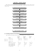
CHAPTER 3. INSTALLATION This chapter describes procedures for installing the RA40C/41C/42C radar in your ship and precautions to be observed during installation. Follow the procedure below to install the radar. Checking contents of your package Checking power supply voltage Determining place of installation Installing scanner unit Installing display unit Connecting cables Adjustment Connecting external equipment When discarding Your radar 3.
The package contains a 10m interconnecting cable as an accessory. also available as an option as listed in Tab.3-1. Longer cable is Tab.3-1 Optional Interconnecting Cable RA40C Product No. 242J160680B 242J160680C Cable length 15m 20m 25m 30m RA41C Product No. 24Y159099B 24Y159099C 24Y159099D RA42C Product No. 24Y159169B 24Y159169C 24Y159169D 242J160680D In addition to the above components included with your package, the following items are also required. Please prepare them separately.
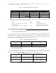
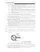
Supply voltage used DC12V DC24V Main Fuse Motor Fuse 10A/250V or 125V (6.3• x 32mm) 8A/250V or 125V * (6.3• x 32mm) 5A/250V or 125V (5•x 20mm) T3.15A/250V or 125V * (5• x 20mm) •••Note: Marked * fuses are in the set as standard. 3.3 Determining Place of Installation 3.3.1 Scanner unit A radar's target detection capacity varies greatly depending on the fitted position of the scanner.
(a) A place where you can see the ship's bow when you raise your face from the radar screen. (b) A place where there is no direct sun-light to avoid display temperature up. (c) A place where there is good ventilation and minimum vibration. (d) A place where the display unit is apart more than the minimum safe distance from a magnet compass as listed in Tab.3-5 below. Tab.3-5 Minimum Safe Distance from Magnetic Compass Scanner unit Display unit Master compass Steering compass 2.0m 1.4m 2.0m 1.4m 3.3.
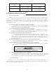
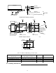
Horizontal line θ Line of sight Fig.
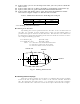
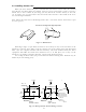
3.4 Installing Scanner Unit When you have decided the place of installation, install the scanner unit. If a mount base like the one shown below is available, it may be easier to install the scanner. If such a mount base is not available in your ship, you may install the scanner directly to the roof, etc. In such a case, pay attention to the water drain tube located at the bottom of the scanner unit during installation.
Chassis Radome(bottom) Mount base Washer Spring washer Included M10 Hexagonal bolt Fix four screws RA40C/41C Radome scanner Forward Forward 12φ × 4 214 (0.47 in.) 199 (7.83Double in.) nuts Spring washer Washer (8.43 in.) 65 170 (2.56 in.) Center 185 (6.69 in.) Rotation Radius (7.28 in.) Scanner baseR550 (3 ft antenna) Mount base R700 (4 ft antenna) 35 M12 Hexagonal14φ bolt× 4 (1.38in.) For air tube 15φ (0.59 in.) Fix four screws Cable inlet 100φ (3.97 in.
Remove the protective cap covering the rotary coupler on the top of the scanner. Match the antenna radiation direction to direction of the arrow markings on the rotation base and fix the antenna in position using the four M8 accessory bolts. Arrow Antenna radiation surface 3.6 Installing Display Unit After you have finished installing the scanner unit, install the display unit in the same way.
! WARNING Avoid a display from operating under direct sunlight. It becomes high temperature at inside of display and display may be broken.
3.7 Connecting Cables Lay cables firmly in place by following the instructions below. Note1: Do not bind the cable for the radar collectively with cables of other equipment (especially power supply cable). Note2: Leave clearance near the inlet of the display so you can remove the display unit easily. This facilitates installation and maintenance of the display unit. (Refer to Appendix.
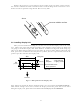
$ Remove the shield cover located on the astern side. (There are four fixing screws.) % Remove the cable clamping plate and rubber ring, pass cable through the introduction opening, put the rubber ring from both ends of it, and clamp the cable to the scanner unit with screws via the fixing plate. Connect 7-pin connector to X11 and 9-pin connector to X12 of PCB. & Replace the aluminum cover. At this time, attach a cable shield onto a ditch with the aluminum cover.
Antenna Stern side Shield cover Cable shield Radome (bottom) Fixing plate Rubber ring Fix connector on PCB(X1) Interconnecting cable Inner shield X1 (Connect here) PCB Radome (bottom) Fig.
Antenna Stern side Shield cover Cable shield Fixing plate Rubber ring Radome (bottom) Fix connector on PCB(X11, X12) Interconnecting cable Inner shield PCB X11 (Connect here) X12 (Connect here) Radome (bottom) Fig.
3.7.2 Interconnecting cable (RA42C Open scanner) (See Fig.3-9) ! Ensure that the radar is off. Connect the cable to the receptacle labeled "SCANNER" on the rear panel of the display unit. " Use a T-wrench to remove the back covers of scanner unit. # Remove the two bolts securing the transceiver; pull out the transceiver after removing two connectors.(to Motor(X1), to Heading switch (X2)) $ Remove the four bolts securing the fixing plate at the cable entrance.
TR unit fixing bolts Remove connector Fixing bolt Clumper Fixing plate Inter-connection cable Fixing bolt Cable shield terminal 5-10 mm Washer Fixing plate Scanner unit Rubber Inter-connection cable Cable inlet Fig.
3.7.3 Grounding wire ! WARNING Connect grounding wire before connecting power supply cable. Leakage current is too high. Connect grounding wire from the grounding terminal on the rear panel of the display unit to the ship's hull as shown below. Grounding wire SCANNER POWER OPTION Grounding terminal Fig.3-10 Grounding display unit to earth Connect grounding wire from one of the bolts you have attached when installing the scanner unit to the ship's hull as shown in Fig.3-11.
3.7.4 Power supply cable Power is fed through a knife switch ( or circuit breaker) and protective fuses, as shown in below. WARNING: Do not apply over 41.6V to Radar or Radar may be broken. Generator Switchboard Main switch panel (Knife Switch with F ses) Storage Battery 12/24V Charger Radar Display Unit DC voltage reference points Fit the power supply cable (included with your radar) to the receptacle labeled "POWER" on the rear panel of the display unit. And connect to power supply as followings.
! TUNING " HEADING DIRECTION # DISTANCE Refer to Adjusting tuning circuit in 5.5.4.5.4 Refer to Adjusting angle in 5.5.4.5.4 Refer to Adjusting distance in 5.5.4.5.4 3.9 Connecting External Equipment to Display Unit The display unit has two channels of NMEA input. One is standard in power cable. The other is necessary to connect optional parts (Junction box with OPTION cable). OPTION connector is located at display’s rear panel for connecting external equipment such as a GPS, LORAN, or gyro compass.
(1) Installation Place of Radar The display unit, scanner unit and inter-unit connection cable should be located apart from the main unit, feeder, antenna coupler and antenna of radio equipment as far as possible. Especially, proper installation of the feeder, antenna coupler and antenna of radio equipment is very important to improve EMI trouble. (2) Laying Power Supply Cables Following connections A and B are recommended to reduce conduction noise generated from radar. Connection C should not be used.