
Installation Instructions

19
3.7 Connecting Cables
Lay cables firmly in place by following the instructions below.
Note1: Do not bind the cable for the radar collectively with cables of other
equipment (especially power supply cable).
Note2: Leave clearance near the inlet of the display so you can remove the dis-
play unit easily. This facilitates installation and maintenance of the dis-
play unit. (Refer to Appendix.)
Note3: Because the cable has a connector fitted on the display and scanner side,
if it is necessary to pass cable through a narrow path, fix the scanner-side
connector vertically using vinyl tape before passing cable through the
path.
Note4: Lay cable along the ship's hull or wall surface and attach it in place at
intervals of about 40 cm.
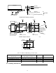
3.7.0 Interconnecting cable (RA40C Radome scanner) (See Fig.3-8-1)
!
Ensure that the radar is off. Connect the cable to the receptacle labeled "SCANNER"
on the rear panel of the display unit.
"
Next, remove the upper part of the radome from the scanner unit. Avoid bumping it
against the antenna by lifting vertically. (There are three fixing screws.)
#
Remove the tape fixing the antenna.
$
Remove the shield cover located on the astern side. (There are three fixing screws.)
%
Remove the cable clamping plate and rubber ring, pass cable through the introduc-
tion opening, put the rubber ring from both ends of it, and clamp the cable to the
scanner unit with screws via the fixing plate. Plug the connector fitted to the cable
into the X1 connector on the PCB.
&
Replace the aluminum cover. At this time, attach a cable shield onto a ditch with
the aluminum cover. However, be careful that the cable will not be caught up be-
tween the main unit and cover.
••
'
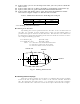
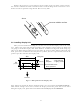
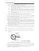
Replace the upper part of the radome. Be careful not to bump it against the antenna
in
the same way as when removing it. Make sure that the cover is fitted in the correct
direc-
tion as shown in Fig.3-7-1. The upper and lower parts of the radome each have
three
markings indicating screw positions. Align the upper and lower positions as you
mount
the radome.
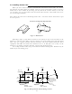
3.7.1 Interconnecting cable (RA41C Radome scanner) (See Fig.3-8-2)
!
Ensure that the radar is off. Connect the cable to the receptacle labeled "SCANNER"
on the rear panel of the display unit.
"
Next, remove the upper part of the radome from the scanner unit. Avoid bumping it
against the antenna by lifting vertically. (There are four fixing screws.)
#
Remove the tape fixing the antenna.
Fixing screws
Ship's
heading
Logo seal on
side wall
Fig.3-7-1 Fitting Cover (RA40C)