
Installation Instructions


26
3.7.4 Power supply cable
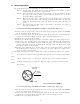
Power is fed through a knife switch ( or circuit breaker) and protective fuses, as shown
in below.
WARNING: Do not apply over 41.6V to Radar
or Radar may be broken.
Fit the power supply cable (included with your radar) to the receptacle labeled "POWER"
on the rear panel of the display unit. And connect to power supply as followings. (When you
do not connect external equipment, put tape on red and green wire.)
Place the Fuse and connection part where there is no water splash and dry area.
When extend the power supply cable, use a suitable cable as below.
Ship's Power Voltage Cable conductor Cable max. length
cross section
12Vdc 3.5 mm
2
3 m
6.0 mm
2
5 m
24Vdc 2.0 mm
2
6 m
3.5 mm
2
10 m
3.8 Adjustment
Be sure to operate the following adjustment. If this
is not adjusted properly, the radar picture does not
display true image.
When you have finished installing the scanner and display units and connecting cables,
turn on the power to the display and scanner units and check to see if they operate nor-
mally without problem. Then make adjustments as detailed below and check to see if the
units operate normally again.
White
Black
Gray
Green
Red
Power supply cable
To dis
p
la
y
unit
DC+
DC-
Ground
NMEA-
NMEA+
To external
equipment
To power supply
Fig.3-12 Power supply cable
!
CAUTION
Generator Switchboard Charger
Storage
Battery
12/24V
Main switch panel
(Knife Switch with
Fses)
Radar Display
Unit
DC voltage
reference points