
Installation Instructions


27
!
TUNING Refer to Adjusting tuning circuit in 5.5.4.5.4
"
HEADING DIRECTION Refer to Adjusting angle in 5.5.4.5.4
#
DISTANCE Refer to Adjusting distance in 5.5.4.5.4
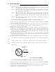
3.9 Connecting External Equipment to Display Unit
The display unit has two channels of NMEA input. One is standard in power cable. The
other is necessary to connect optional parts (Junction box with OPTION cable).
OPTION connector is located at display
’
s rear panel for connecting external equipment
such as a GPS, LORAN, or gyro compass. You must have an Junction box with OPTION ca-
ble. (Refer to CHAPTER 8 (4) External interface.)
Note: SIN/COS and MOB signals cannot be used on Junction Box.
Junction box with OPTION cable (Order No. RZ704A)
3.10 Countermeasure for Electromagnetic Interference
RA40C/41C/42C radar provides shields in the units and the inter-unit connection ca-
ble. When the radar, however, is closely installed to radio equipment such as VHF trans-
ceiver, UHF transceiver, etc., or the radar and/or radio equipment are not sufficiently
grounded to the hull or ship's earth, the radar may happen to cause EMI trouble.
Followings are general procedures for reducing EMI due to radars. When installing ra-
dars, refer to them, and also check the radio equipment EMI trouble with operating the ra-
dar and radio equipment.
SCANNER
POWER
OPTION
OPTION cableJunction box*
note
POWER cable
External NMEA equipment
External NMEA equipment
Green :NMEA-
Red :NMEA+
To power supply
Other radar,
slave monitor,
External buzzer,
Gyro I/F
Other radar,
slave monitor,
External buzzer,
Gyro I/F,
SIN/COS.
MOB(NMEA out)
Fig.3-13 Connecting external equipment to display unit