
Installation Instructions


28
(1) Installation Place of Radar
The display unit, scanner unit and inter-unit connection cable should be located
apart from the main unit, feeder, antenna coupler and antenna of radio equipment as
far as possible.
Especially, proper installation of the feeder, antenna coupler and antenna of radio
equipment is very important to improve EMI trouble.
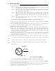
(2) Laying Power Supply Cables
Following connections A and B are recommended to reduce conduction noise gener-
ated from radar. Connection C should not be used.
Connection A
(Very Good)
Connection B
(Good)
Connection C
(Bad)
(3) Grounding
All equipment should be firmly grounded at the earth nearest hull with copper plates
or braided wires.
Improvement Procedure for EMI
(1) Confirm grounding on the radar and radio equipment. However, some equipment, on
which grounding is not always necessarily, have a possibility of EMI improving when
taking off their grounding. Try to take off grounding.
(2) Confirm power supply cable connections and modify to the connection A or B above.
(3) Try to shift the display unit and inter-unit connection cable of radar to be apart from
radio equipment.
(4) Try to shift the feeder of radio equipment to be apart from each units and the inter-
unit connection cable of radar.
(5) Try to shift the antenna coupler and antenna of radio equipment to be apart from
the scanner unit and inter-unit connection cable of radar.
3.11 When Discarding Your Radar
When discarding your RA40C/41C/42C radar, consult the distributor to get informa-
tion on precautions to be followed. Tab.3-7 below lists the primary component materials of
the RA40C/41C/42C radar for your reference.
Tab.3-7 Component Materials
Scanner unit Material Display unit Material
Radome
AES
Front panel
ABS
Chassis
A5052P
Rear panel
ADC12
Base
ADC12
Pedestal
ABS+PC
Antenna
A5052P
RADAR
RADIO EQUIPMENT
SHIP'S SUPPLY
SHIP'S SUPPLY
RADAR
RADIO EQUIPMENT
SHIP'S SUPPLY
RADAR
RADIO EQUIPMENT
SHIP'S SUPPLY