
Installation Instructions


11
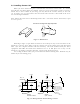
The package contains a 10m interconnecting cable as an accessory. Longer cable is
also available as an option as listed in Tab.3-1.
Tab.3-1 Optional Interconnecting Cable
In addition to the above components included with your package, the following items
are also required. Please prepare them separately.
Item QTY Remarks
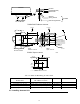
Tapping screw or M5 bolt and nut 6 sets To install display unit
Grounding wire 1 Earth line for display unit
Grounding wire and crimp terminal 1 set Earth line for scanner unit
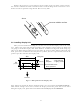
3.2 Checking Power Supply Voltage
3.2.1 Power Supply Requirements
For the RA40C/41C/42C radar to be operated normally, the power supply (battery)
detailed in Tab.3-2 is required. Note also that if the battery is discharged, its voltage may
fluctuate greatly, causing the radar to malfunction. When start up the radar system or start
transmitting, an additional rush current is required on the power line. Carefully check the
power supply system including wiring by using a circuit tester.
Tab.3-2 Power Supply Requirements
*A.C. power cannot be used
3.2.2 Fuse Replacement
For the RA40C/41C/42C radar to be operated safely, proper rating fuses must be
used. Tab.3.3 and Tab.3.4 are fuse rating tables for RA40C/41C and RA42C. Check them
and replace to the fuse in the package.
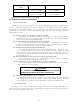
Tab.3-3 Supply Voltage to Fuse Table for RA40C/41C
Tab.3-4 Supply Voltage to Fuse Table for RA42C
RA40C RA41C RA42C
Cable length Product No. Product No. Product No.
15m 242J160680B 24Y159099B 24Y159169B
20m 242J160680C 24Y159099C 24Y159169C
25m 24Y159099D 24Y159169D
30m 242J160680D
Supply voltage
used
Maximum current Allowable range of voltage
DC12V 5A 10.2-41.6V
DC24V 2.5A 10.2-41.6V
Supply voltage
used
Main Fuse Motor Fuse
DC12V 8A/250V or 125V *
(6.3
•
x 32mm)
T3.15A/250V or 125V *
(5
•
x 20mm)
DC24V 8A/250V or 125V
(6.3
•
x 32mm)
T3.15A/250V or 125V
(5
•
x 20mm)