
Installation Instructions

15
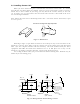
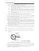
3.4 Installing Scanner Unit
When you have decided the place of installation, install the scanner unit. If a mount
base like the one shown below is available, it may be easier to install the scanner. If such a
mount base is not available in your ship, you may install the scanner directly to the roof,
etc. In such a case, pay attention to the water drain tube located at the bottom of the scan-
ner unit during installation.
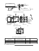
Note : When the radar mast or mounting bracket has a curvature of more than 2mm, repair
it or use spacers.
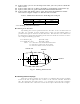
Referring to Fig.3-4, open holes in diameter of 12 mm (0.47 in.) at five locations in the
mount base and use these holes to fix the scanner unit to the mount base with hexagonal
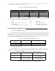
bolts. (Use the template included with this manual.) The bolts included with your radar
equipment will suffice for mount base thickness of 9 to 14 mm (0.35 to 0.55 in.). If the
mount base is thicker or thinner than this, prepare bolts listed in Tab.3-6.
Use sealing of silicon when you prevent the bolts from becoming loose. Radome may be
broken if you use locking putty.
Do not use an edge that might trap water.
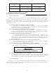
Fig.3-3 Mount base
Center
214
170
12
φ
×
4
Unit:mm
65
Forward
(8.43 in.)
(2.56 in.)
(0.47 in.)
35
(1.38in.)
For air tube
(6.69 in.)
15
φ
(0.59 in.)
199
(7.83 in.)
Forward
185
(7.28 in.)
Rotation Radius
R550 (3 ft antenna)
R700 (4 ft antenna)
14
φ
×
4
(0.55 in.)
Cable inlet
100
φ
(3.97 in.)
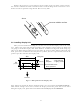
RA41C
Radome scanner
RA42C
Open scanner
Fig.3-4 Hole positions for mounting scanner