
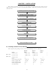
Installation Instructions

17
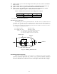
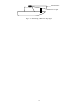
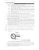
Remove the protective cap covering the rotary coupler on the top of the scanner. Match
the antenna radiation direction to direction of the arrow markings on the rotation base and
fix the antenna in position using the four M8 accessory bolts.
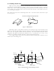
3.6 Installing Display Unit
After you have finished installing the scanner unit, install the display unit in the same
way. Choose the proper bolt length according to the thickness of the surface on which you
are going to install the display unit. Hole diameter is different using bolts from using tap-
ping screw. When using tapping screw, open holes in adequate holes. When using bolts and
nuts, open holes in diameter of 6 mm (0.24 in.). When you have opened holes, install the
pedestal part first and then the display unit.
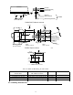
Note : When you install the display by flush mount, refer to appendix "OUTLINE DRAWING".
Slide off four triangle corner cover, and fix the display unit to the panel with screws. After
fixing the display unit,
put on corner covers to the corner of the display unit. See APPENDIX.
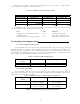
360
84
Fitting hole
(14.17 in.)
(3.31 in.)
Hole diameter
6mm : Bolts and Nuts
Adequate : Tapping screws
Recommended screw
M5 or equivalent
Unit : mm
47
(1.85 in.)
37
(1.46 in.)
60
(2.36 in.)
240
(9.45 in.)
60
(2.36 in.)
Forward
Fig.3-6 Hole positions for display unit
Antenna radiation surface
Arrow