
Installation Instructions

3
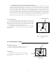
Beam width
A beam width is defined as the width of the main lobe at an angle where the radi-
ated power is halved as measured from the position from which the strongest radio
wave is radiated.
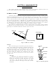
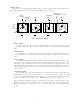
2.2 Characteristics of Radar Wave
Radio waves from the radar propagate while bending slightly along the terrestrial sur-
face. This characteristic varies dependent on the density of the atmospheric air. The sight
distance D of a radar generally is said to be approximately 6% longer than the optical sight
distance and is calculated using the equation below :
D (NM) = 2.22 ( h1 + h2 ) where, h1= antenna height in meters
h2= target height in meters
Fig.2-3 Radar wave
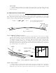
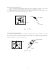
Targets difficult to display on screen
The intensity of the reflected wave from a target depends on the distance, height,
and size of the target, as well as its material and shape. Targets constructed with
FRP, wood, or other low-reflectance materials or those that have a small incident angle
are difficult to display on a screen. Therefore, FRP and wooden ships, sandy beaches,
and sandy or muddy shallows all are difficult to catch and require attention when
monitoring on the screen. Especially, coast lines on the radar image appear to be pre-
sent more apart from the ship than they are actually located. Therefore, it is important
not to misinterpret the available data.
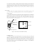
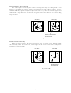
Shadow zones of radar
Radar waves are characteristic in that they propagate straight ahead. Therefore,
if the ship's smokestack or mast is located near the antenna or there is a tall ship or
mountain at the side of the ship, such an object generates a shadow behind it. In this
Apparent coastline
Actual(invisible)
coastline
Invisible
Visible
3
1
HU
Fig.2-4 Targets difficult to display on screen
h1 h2
Line of sight
Radar Radio
Wave
Earth