
User Manual

89
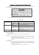
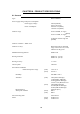
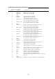
8.9 External Connection and function
X1 Connector for Option
pin No. Name function
1 NMEA2-A NMEA ch2 data input(A)
19 NMEA2-B NMEA ch2 data input(B)
2 GND
20 EXBUZ+ Output for External Buzzer
3 EXBUZ- Output for External Buzzer
controlled ship's power output
21 VIDEO_IN Video input for Monitor operation
0 to -1V negative video, Zi = 50ohm
4 VIDEO_OUT Video output for External Monitor
0 to -1V negative video, Zo = 50ohm
22 GND
5 TRIG_IN Trigger signal input for Monitor operation
0 to 5V positive pulse, rising edge
23 TRIG_OUT Trigger output for External Monitor
0 to 5V positive pulse, rising edge
6 SHF_IN Heading signal input for Monitor operation
0 to 5V negative pulse, falling edge
24 SHF_OUT Heading signal output for External Monitor
0 to 5V negative pulse, falling edge
7 AZI_IN Bearing Pulse input for Monitor operation
0 to 5V positive pulse, rising edge
25 AZI_OUT Bearing Pulse output for External Monitor
0 to 5V positive pulse, rising edge
8 GND
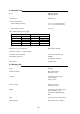
26 GYRCK+ Gyro Interface clock(+) input
9 GYRCK- Gyro Interface clock(-) input
apply 5V pulse between (+) and (-), isolated
27 GYRDT+ Gyro Interface data(+) input
10 GYRDT- Gyro Interface data(-) input
apply 5V pulse between (+) and (-), isolated
28 GND
11 MARK_I External Marker signal input, ex) Radar Buoy
negative video, 0 to -1V Zi = 50ohm
29 +12V External interface power, 100mA max.
12 SIN Compass Interface for SIN/COS type
30 COS Compass Interface for SIN/COS type
13 REF Compass Interface for SIN/COS type
SIN/COS signal: SIN = REF+/-1V, COS = REF+/-1V
31 -- not used
14 GND
32 NMEA_OUT NMEA data output, ex) MOB data, TARGET data