
User Manual

78
5.6 ATA Operation
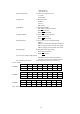
5.6.1 ATA Board Specifications
(1) Acquisition Manual
A target is acquired manually by a cross cursor driven
by the Pointing Device.
(2) Tracking Automatic
(3) Number of tracked targets 10 targets maximum
(4) ATA data output Target Number, distance, bearing, speed, course,
CPA and TCPA
(5) Alarm Collision alarm, activated when a target enters
the preset CPA and TCPA ranges.
Lost alarm, activated when a target can no longer
be tracked.
(6) Display Symbols: Predicted point and target number
Vector : Predicted motion of a target as a result of
own ship's direction and speed input.
Display modes: Relative (REL)/True (TRUE)
(7) Tracking range 0.5 to 40 NM
(8) PRF 2,000 Hz maximum
(9) Bearing signal 1,080 or 2,048 pulses / rev (Switched automatically)
See Note.
Note: The ATA board does not accept bearing signals other than specified above. In case the ATA board is
used in the monitor mode display, make sure an incoming bearing pulse rate agrees with that specified in this
specification.
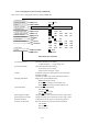
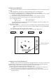
5.6.2 Operating Instructions
5.6.2.1 Outline
The ATA detects a target from radar image signals and measures the distance from the target and its bearing
automatically. By calculating changes in the measurement results to predict the target movement, the ATA
tracks the target automatically.
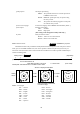
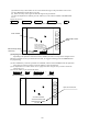
The ATA calculates the CPA (closest point of approach) and the TCPA (time required for the ship to reach
the CPA) from the movement of the target toward the ship. Then comparing them to those preset, it generates
a collision alarm if both values are smaller than the preset ones.
The target bearings are calculated by (1) bearing of the target toward the ship and (2) bearing of the ship's
heading marker. Therefore, the accuracy of the data on the heading marker's bearing affects tracking per-
formance. Tracking may become impossible if the compass is inaccurate and especially when the ship is
yawing or changing the course. These cases, however, are not caused by a malfunction of ATA.
5.6.2.2 Setting
Before using the ATA function, the settings described below are necessary.
Note: Use the ATA function in either the PPI or ALL PPI mode. Even if other modes are used, the ATA
still continues tracking though the symbols and data are not displayed on the radar.
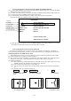
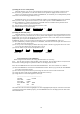
(1) Switching the ATA function ON/OFF
Select the ATA PRESET items from the SET UP/CUSTOM menu.
The menu contents are as follows.
-------------------------------------------------------
CPA SET 0.0 NM
TCPA SET 0 MIN
VECT SET 6 MIN
VECT MODE REL TRUE
ATA ON OFF
-------------------------------------------------------
Check that ON in the ATA items is highlighted. If OFF is highlighted (selected), the ATA does not function.
* Unless the ATA board is installed properly, the ATA PRESET items are not displayed on the above SET
UP/CUSTOM menu.