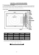
CHAPTER 4. FUNCTIONS AND NAMES Function and name of each part The RA53/54 radar consists of a display unit to display video images on a screen and a scanner unit configured with an antenna to radiate radio waves and other components. The display unit has on its front panel eighteen(18) push-switch keys and one cursor key that lets you move a cursor in any desired direction. A combination of these keys allows you to utilize all functions of your radar, providing a comfortable, easy way to operate. 4.
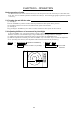
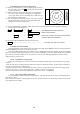
4.2 Rear panel 1. Power supply connector Use this connector to plug in the power supply cable. Standard NMEA interface terminal is included in this connector. Refer to Section 3.7 “ Connecting Cables “ and Section 3.9 “Connecting External Equipment to Display Unit “. 2. Grounding terminal Use this terminal to connect grounding wire. Refer to Section 3.7 (3) “Grounding wire”. 3. Option connector Use this connector to connect NMEA, an external monitor, external buzzer and GYRO I/F.
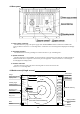
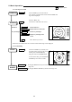
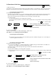
4.4 Radar screen (Dual screen) ex) PPI/PPI screen Range(Left screen) Range ring interval (Left screen) 6 1.0_ HU L Range(Right screen) Range ring interval (Right screen) .75 Tune meter Picture hold A .25 HOLD EBL1 Display mode VRM1 + Pulse width EBL2 Indicate soft key VRM2 Cross cursor FL EBL2 FL VRM2 Cruising speed Heading angle Course error EBL1 VRM1 Guard zone(Right screen) Guard zone(Left screen) SPD HDG +MK 0.23 XTE >>> 1 129.8° 1 12.34NM Cross coursor position 12.8KT 129.2° 38.4° 5.
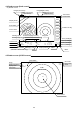
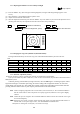
.6 Radar screen (All PPI /PPI screen) Range(Left screen) Range ring interval (Left screen) 6 1.0_ HU L GZ IN Range(Right screen) Range ring interval (Right screen) .75 .25 GZ IN HOLD Picture hold Guard zone(Right screen) Display mode Guard zone(Left screen) + Pulse width Cross cursor 4.7 Navigation screen NAV DISPLAY WP Way point 134.4° 12.5 NM Heading angle HDG 129.0° Cruising speed SPD 12.8KT Current position LAT 35°08.42N LON 139°02.53E Sea water temperature TEMP 20.
CHAPTER 5. OPERATION Basic operation of radar The RA53/54 radar has several fixed-function keys on the front panel. Press the relevant key to control these functions. Also, you can customize particular functions to the soft-keys. The following paragraphs explain the operation of each key. 5.1 Turning On and Off the radar (1) Turning On Press the "POWER" key. Buzzer sounds a short beep and then the radar system will be powered.
5.3 Basic Operations xxx = Keys to press 5.3.1 Turning On and Off POWER ON POWER Press POWER key to turn the radar on. The 2 minute countdown timer starts and the RADAR OFF sign will be displayed. Press the "BRIL" key. SCREEN BRILL Control bar is indicated on the screen. .75 Brilliance Key backlight Up/Down Select brilliance. Control knob Adjust brilliance with knob. Up/Down Select key backlight. Control knob Adjust key backlight with .25 HU 1:58 RADAR OFF + knob.
5.3.3 Adjusting the brilliance of screen and key-backlight xxx = Keys to press (1) Press the "BRILL" key. (Bar and figure indicating brightness, and figure indicating backlight appears on the screen.) (2) Select brilliance or key-backlight with the up-down cursor. (3) Adjust each item with the control knob. (4) When the adjustment is finished, press either the "BRILL" key or the "ENT" key to exit from the adjustment screen.
REMINDER: * What happens if GAIN, STC, and FTC keys are pressed during AUTO operation? 1) If GAIN key is pressed, Only GAIN enters a manual state. 2) If FTC key is pressed, Only FTC enters manual state. 3) If STC key is pressed, STC, GAIN, and FTC enter manual state. 5.3.6 Sensitivity adjustment (GAIN) (1) When you press the "GAIN" key, the GAIN display on the left side of the screen will be reversed as G 35 , allowing the manual gain adjustment to be effective.
5.3.8 Removing rain and snow clutter (FTC) (1) When you press the FTC key, the FTC display on the left side of the screen will be reversed as F 50 , allowing the manual control of FTC to be effective. (2) When you turn the control knob either CW or CCW, the figure will change within a range of 0 through to 99, changing the receiver gain. When you press the AUTO key, GAIN, STC and FTC will be set to AUTO mode. (3) After the adjustment is finished, press the "FTC" key to exit from the adjustment mode.
5.4 Functions of Soft Keys xxx = keys to press < Outline of soft keys > Any function can be optionally allocated to the key upon which numbers 1-7 are indicated. A maximum of 4 groups of functions can be allocated to each soft key, and switching between those functions is conducted by the "NEXT" key. 5.4.
5.4.4 Distance measurement (VRM2) The operation is the same as VRM1, refer to VRM1 operation. The "VRM2" will appear in a reverse display at the lower right side of the screen. 5.4.5 Measuring the angle between two points (FL EBL2) Note: VRM2 and EBL2 do not follow the OFF-C function while floating. Note: Refer to "5.5.1.5 Measuring the distance or angle between two points ( FL EBL2, FL VRM2 )". (a) Setting a reference point for measurement of the angle. (1) Press "FL EBL2" key.
Operation_ NEXT 7 NEXT NEXT 7 7 NEXT 7 _Soft Key Setting Example_ SET1 EBL1 SET2 SET3 SET4 1 EBL2 1 DATA 1 PPI 1 VRM1 2 VRM2 2 DEL 2 PPI/3D 2 VAR RNG 3 FL EBL2 3 TRACK 4 FL VRM2 4 TRACK 4 PPI/NAV 4 GZ 5 ZOOM 5 ALL PPI 5 OFF-C 6 PICTURE 6 ALL PPI2 6 NEXT 7 TARGET 5 SEL WIN 6 NEXT 7 NEXT ALL-DEL 3 7 PPI/PPI 3 NEXT 7 The function can be changed at the "KEY ASSIGNMENT" function in the "CUSTOM" menu of the "SETUP". 5.4.
note: TM is valid on PPI screen only. The mode will change to NU on the other screen automatically. Note: Refer to "5.5.2.1 Changing display mode (MODE)". 5.4.13 Guard Zone (GZ) A function that sets a guard zone of any distance and any angle range, creating an alarm tone when either echoes above a certain level exist (IN MODE) or no echoes exist(OUT MODE).
5.4.15 Setting of the SLEEP function (SLEEP) This function allows the transmitter to transmit 30-seconds during pre-fixed hours. After a transmission, a power-saving mode is entered with the screen put into the ST'BY mode (the scanner is kept OFF state) and the LCD backlight lamp is turned off. This action is repeatedly executed. For example, set a guard zone and set the warning signal automatically confirmed every prefixed period. Press the "SLEEP" key to set up the sleep period.
sec → 30 sec → 1 min → 3 min → 6 min → CONT → OFF Note: The "OFF" state will not be displayed on the screen and the "TK xx " display will disappear. 5.4.19 Enlarging selected areas (ZOOM) The video image shown around the cross cursor can be zoomed twice as large as normal one on the screen. Press the "ZOOM" key to "ZOOM" ON. A small cross cursor and the sign "SET ZOOM POINT" will be displayed on the screen center and at the bottom respectively, and the magnification point is to be set.
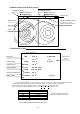
5.4.22 Changing the color of screen (PICTURE) The display color can be changed according to daytime or nighttime operations. Press the "PICTURE " key to change the color. Note: Refer to "5.5.4.3 Changing the color of screen (PICTURE)". 5.4.23 Change to PPI screen ( PPI ) Press the "PPI" key to change the screen to the standard single PPI screen. . 75 .25 HU + PPI screen .75 .25 HU S 5.4.
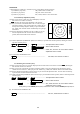
5.4.26 Change to PPI/NAV screen ( PPI/NAV ) Press the "PPI/NAV" key to change current screen mode to PPI/NAV screen mode. Note: The ZOOM, OFF-C, FL EBL2, and FL VRM2 can not be used in this mode. .75 .25 HU s NAV DISPLAY + WAY P 123.4° 6.8NM COURSE 2.38NM XTE <<<< HDG 267.3°T SPD 12.8KT TEMP 20.8°C DEPTH 58.3M LAT/LON 34° 08. 22N 138° 02 .53E PPI/NAV screen 5.4.27 Change to ALL PPI screen ( ALL PPI ) Press the "ALL PPI" key to change the current screen mode to ALL PPI screen mode.
When operating from the MENU, place the cursor on NAVI/DATA and press the ENT key. Items to be displayed are as follows. Target number: TGT NO.x The number of the target currently displayed. Vector time: TIME xx MIN. Setting time to display vector length. (Speed x Time=vector length) Vector mode: TRUE or REL Display mode of vector and data. TRUE and REL represent true and relative speeds, respectively.