
User Manual

29
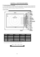
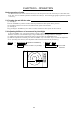
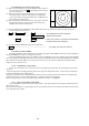
4.2 Rear panel
1. Power supply connector
Use this connector to plug in the power supply cable. Standard NMEA interface terminal is included in this
connector. Refer to Section 3.7 “ Connecting Cables “ and Section 3.9 “Connecting External Equipment to Display
Unit “.
2. Grounding terminal
Use this terminal to connect grounding wire. Refer to Section 3.7 (3) “Grounding wire”.
3. Option connector
Use this connector to connect NMEA, an external monitor, external buzzer and GYRO I/F. A dedicated cable or
dedicated module box is required to connect these pieces of equipment. Refer to Section 3.9 “Connecting Ex-
ternal Equipment to Display Unit”.
4. Scanner connector
Use this connector to plug in the inter-connecting cable to connect the scanner unit.
Refer to 3.7 “Connecting cable “.
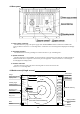
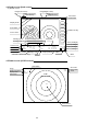
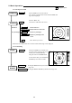
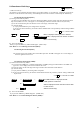
4.3 Radar screen( Single screen )
Ship’s position
EBL2
VRM2
Indicate soft key
3
1
HU L
1:58
+
RADAR OFF
EBL1
VRM1
EBL2
VRM2
FL EBL2
FL VRM2
NEXT
A
HOLD
ZOOM
OFF-C
LAT/LON
35°08. 42N
139°02. 53E
2 129. 8°
2 12. 34NM
0.23NM
HDG
129.0 °T
SPD
12.0 KT
G 59
S AT
F AT
ST1
GZ IN
TK 15 S
WP
134.4 °
12.5NM
+LAT/LON
35°08.42N
139°02.53E
1 129. 8°
1 12. 3NM
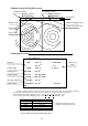
Tune meter
Picture hold
Zoom
Off-center
Range
Range ring interval
Display mode
Heading angle
Cruising speed
Enlarging echo
Guard zone
Track
Way point
EBL1
VRM1
Pulse width
Course error
Gain
STC
FTC
Cross cursor
Cross cursor position
(LAT/LON or Distance/Bearing)