
Instruction Manual


18 RA51/52/53/54/55 INSTRUCTION MANUAL – 05
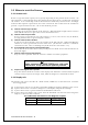
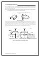
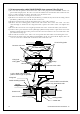
3.7.2 Interconnecting cable (RA52/53/54/55 Open scanner) (See Fig.3-9)
1) Be sure that the power is off. Connect the cable to the plug labeled "SCANNER" on the rear
panel of the display unit. Be sure to secure the rubber boot around the cable connector rim.
2) Use a socket wrench to remove the back cover of scanner unit.
3) Remove the two bolts securing the transceiver.
4) Remove the connectors to the motor (X1:RA52, J5:RA53/54/55) and to the heading switch
(X2:RA52, J3:RA53/54/55). Pull out the transceiver.
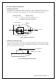
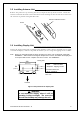
5) Remove the four bolts securing the fixing plate at the cable entrance.
6) Remove the metal fixing plate, rubber seal and washer that secure the cable. Pass the
cable through as shown in the diagram below; replace the above items and tighten the
bolts.
7) Return the transceiver to its original position and secure it with the bolts you removed.
8) Connect the 7-pin connector to X11 (RA52)/J1 (RA53/54/55) and the 9-pin connector to X12
(RA52)/J2 (RA53/54/55) of the printed circuit board and connect the two connectors that
you removed in Step 3).
9) Reattach the scanner cover. Take care not to pinch the cable when reattaching the cover.
10) Connect the cable to the plug labeled "SCANNER" on the rear panel of the display unit. Be
sure to secure the rubber boot around the cable connector rim.
TR unit fixing bolts
Remove connector
Fixing bolt
Fixing plate
Inter-connection cable
Clamp
MAX 5 mm
Fixing bolt
Cable shielding terminal
Washer
Fixing plate
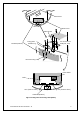
Scanner unit
Inter
-
connection cable
Sealing rubber
Cable inlet
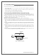
When covered with heat-sink tube,
remove any heat-shrink tube.
Lay the braid under the fixing
plate in short length as possible.