
Instruction Manual


20 RA51/52/53/54/55 INSTRUCTION MANUAL – 05
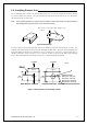
3.7.4
Power
supply cable
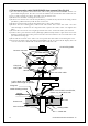
Power should be fed through a switch and protective fuses (or circuit breakers), as shown be-
low.
WARNING: Do not apply over 41.6V to the unit
or it may be damaged.
Plug the power supply cable into the connector labeled "POWER" on the rear panel of the
display unit. If you don not connect your radar to external equipment, tape the ends of the red
and green wires. Be certain to locate the fuse where it will be kept dry.
When extending the power supply cable, size the wire as follows:
Boat Power Voltage Cable conductor Cable max. length
cross section
12Vdc 10 AWG (3.5 mm
2
) 3 m
8 AWG (6.0 mm
2
) 5 m
24Vdc 12 AWG (2.0 mm
2
) 6 m
10 AWG (3.5 mm
2
) 10 m
Fig.3-12 Power supply cable
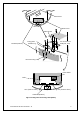
3.8 Adjustment ___________________________________________
Be sure to make the following adjustments. If not
the radar will not display a true image.
When you have finished installing the scanner and display units, turn on the power to see if
they operate. Then make adjustments as detailed below:
•
TUNING Refer to Adjusting tuning circuit in 5.5.4.6.5
‚
HEADING DIRECTION Refer to Adjusting angle in 5.5.4.6.5
ƒ
DISTANCE Refer to adjusting distance in 5.5.4.6.5
!
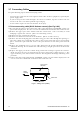
CAUTION
Generator
Switchboard
Charger
Storage
Battery
12/24V
Main switch panel
(Knife Switch with Fuses)
Radar Display
Unit
DC voltage
reference points
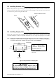
White
Black
Gray
Green
Red
Power supply cable
To display unit
DC+
DC-
Ground
NMEA (B)
NMEA (A)
To external equipment
To power supply