
Instruction Manual


RA51/52/53/54/55 INSTRUCTION MANUAL – 05 21
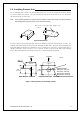
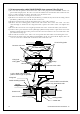
3.9 Connecting External Equipment to Display Unit ____________
The display unit has connections for two NMEA interface ports. One is made through the
power cable. The other is accessed through the OPTION connector on the display's rear
panel. A separate cable and optional junction box are needed to use this interface. (Refer to
CHAPTER 8 (4) External interface.)
Note: SIN/COS and MOB/TARGET signals cannot be accessed through the junction box interface.
Junction box with OPTION cable (Order No. RZ704A)
Fig.3-13 Connecting external equipment to display unit
3.10 Countermeasure for Electromagnetic Interference ___________
The RA51/52/53/54/55 radar uses internal shields and shielded cable to minimize elec-
tro-magnetic interference (EMI). However, when the unit is placed close to a radio trans-
ceiver and either piece of equipment is not properly grounded, the radar will cause inter-
ference.
Here are some hints on how to reduce EMI due to radar.
(1) Installation Location
The display unit, scanner unit and interconnecting cable should be located as far as possible
from the transceiver, antenna cable and antenna of the radio. Experiment with various posi-
tions of both to see if it improves the condition.
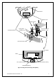
(2) Laying Power Supply Cables
The best solution is to run separate power wires from each unit directly to the boat's electrical
supply source. A connection should be made at the main breaker panel or as close to the
generator or battery as possible. Connection A and B are recommended. Connection C should
not be used.
OPTION connector
(249J153058)
Junction box*
note
(RZ704A)
POWER cable
External NMEA equipment
(GPS,LORAN,etc.)
External NMEA equipment
(GPS,LORAN,etc.)
Red :NMEA (A)
Green :NMEA (B)
To power supply
Other radar,
slave monitor,
External buzzer,
Gyro I/F
Other radar,
slave monitor,
External buzzer,
Gyro I/F,
SIN/COS.
MOB(NMEA out)
External NMEA equipment
(GPS,LORAN,etc.)