
Instruction Manual


10 RA51/52/53/54/55 INSTRUCTION MANUAL – 05
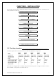
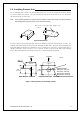
Tab.3-1 Optional Interconnecting Cable
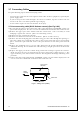
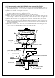
You'll need to supply the following hardware:
Item QTY Remarks
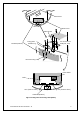
Tapping screw or M5 bolt and nut 6 sets To install display unit
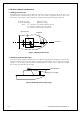
Grounding wire 1 Earth line for display unit
Grounding wire and crimp terminal 1 set Earth line for scanner unit
3.2 Checking Power Supply Voltage___________________________
3.2.1 Power Supply Requirements
Tab.3-2 shows the power requirements for the RA51/52/53/54/55 radar. If the unit is supplied
with less than the specified voltage, it won't operate properly. Keep in mind that when the
unit is initially powered on there will be a peak current surge. Check all circuits back to the
power source for correct wire gauge and tight connections.
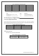
Tab.3-2 Power Supply Requirements
*A.C. power cannot be used
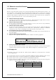
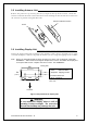
3.2.2 Fuse
Replacement
CAUTION: Use only exact replacements.
Tab.3-3 Supply Voltage vs. Fuse Ratings
Main Fuse Motor Fuse
15A/250V or 125V *
(6.3F x 32mm)
T3.15A/250V or 125V
(5F x 20mm)
RA51 RA52/53/54 RA55
Cable length Product No. Product No. Product No.
10m(If you need) 242J158055A
15m 242J158055B 242J159098B
20m 242J158055C 242J159098C 242J159098C
30m 242J158055D 242J159098D 242J159098D
Supply voltage used
Maximum current
Allowable range of voltage
DC12V 14A 10.2-41.6V
DC24V 6A 10.2-41.6V
DC24V (for RA55) 15A 18.0-41.6V