
Instruction Manual


RA51/52/53/54/55 INSTRUCTION MANUAL – 05 13
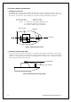
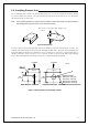
3.4 Installing Scanner Unit _________________________________
Use a mounting base such as the ones shown in Fig. 3.3, or you can install the scanner directly
to a roof or other flat surface. Be certain you keep the water drain tube clear. It's located at
the bottom of the scanner unit.
Note : If the mounting bracket or surface has a curvature of more than 2mm, use spacers with the
mounting bolts to prevent stress on the scanner housing.
Fig.3-3 Mount base
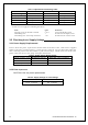
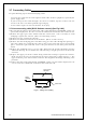
Use the template provided with this manual to drill five holes for mounting the scanner. At-
tach the four bolts and feed the drain tube through the fifth hole. The bolts included with your
unit will suffice for mount base thickness of 9 to 14 mm (0.35 to 0.55 in.). If the mount base is
thicker or thinner, refer to Tab.3-6. Use a silicone sealant to prevent the bolts from working
loose. The housing may be damaged if you use a thread-locking compound.
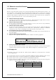
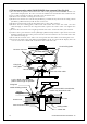
Fig.3-4 Hole positions for mounting scanner
Do not use an edge that might trap
water.
Center
214
170
12
φ
×
5
Unit:mm
65
Forward
(8.43 in.)
(2.56 in.)
(0.47 in.)
(6.69 in.)
199
(7.83 in.)
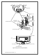
Forward
185
(7.28 in.)
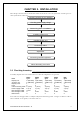
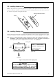
Rotation Radius
R550 (3 ft antenna)
R700 (4 ft antenna)
R1000 (6 ft antenna)
R1400 (9 ft antenna)
RA51 Radome scanner
RA52/53/54/55 Open scanner