
Instruction Manual


RA51/52/53/54/55 INSTRUCTION MANUAL – 05 15
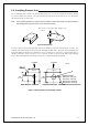
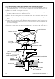
3.5 Installing Antenna Unit_________________________________
Remove the protective cap covering the rotary coupler on the top of the scanner. Match the
antenna radiation direction to direction of the arrow markings on the rotation base and secure
the antenna in position using four M8 bolts.
Antenna radiation surface
Arrow
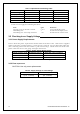
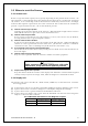
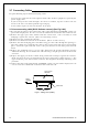
3.6 Installing Display Unit__________________________________
Choose the proper bolt length according to the thickness of the surface on which you are going
to install the display. Hole size depends on whether you are using self-tapping screws or bolts.
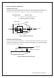
Note : When you install the display by flush mounting to a panel, refer to appendix "OUTLINE
DRAWING". Slide off the four triangular-shaped corner covers, and attach the display unit
to the panel with screws. Replace the corner covers. See APPENDIX.
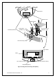
Fig.3-6 Hole positions for display unit
Do not mount the display where it will be
operating in direct sunlight. The excessive
internal heat buildup may damage the unit.
360
84
Fitting hole
(14.17 in.)
(3.31 in.)
Hole diameter
6mm: Bolts and Nuts
Adequate: Tapping screws
Recommended screw
M5 or equivalent
Unit : mm
47 (1.85 in.)
37 (1.46 in.)
60
(2.36 in.)
240
(9.45 in.)
60
(2.36 in.)
Forward
!
WARNING