
Instruction Manual
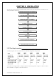


16 RA51/52/53/54/55 INSTRUCTION MANUAL – 05
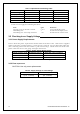
3.7 Connecting Cables _____________________________________
Keep the following tips in mind when laying cables:
- Do not tie the cables for the radar together with cables of other equipment, especially the
power supply cable.
- If you need to pass the cable through a wire chase or conduit, tape the scanner side con-
nector to the wire so it doesn't pull off or get hung up.
- Secure cables in place at intervals of about 40 cm (16").
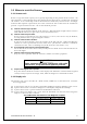
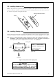
3.7.1 Interconnecting cable (RA51 Radome scanner) (See Fig.3-8-2)
1) Be sure that the power is off. Connect the cable to the plug labeled "SCANNER" on the rear
panel of the display unit. Be sure to secure the rubber boot around the cable connector rim.
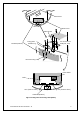
2) Remove the upper part of the radome from the scanner unit. Lift it vertically to avoid
bumping it against the antenna. (There are four fixing screws.)
3) Remove the tape securing the antenna.
4) Remove the shield cover located on the backside. (There are four screws.)
5) Remove the cable clamping plate and rubber ring, pass the cable through the opening, re-
place the rubber ring, and clamp the cable to the scanner unit with screws on the fixing
plate. Attach the 7-pin connector to X11 and 9-pin connector to X12 of the printed circuit
board.
6) Replace the aluminum cover. Lay the cable shield into the channel machined into the
aluminum housing. Be careful that the cable will not get caught up between the main unit
and cover.
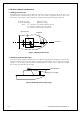
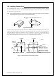
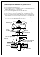
7) Replace the upper part of the radome being careful not to bump it against the antenna.
Make sure that the cover is positioned in the correct direction as shown in Fig.3-7. The
upper and lower parts of the radome each have four alignment markings indicating screw
positions.
8) Connect the cable to the plug labeled "SCANNER" on the rear panel of the display unit. Be
sure to secure the rubber boot around the cable connector rim.
Ship's
heading
Logo seal on
side wall
Fix four screws
Cable inlet
Fig.3-7 Fitting cover (RA51)