
Datasheet

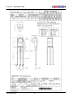

Parts No: KSM-200□LN2M
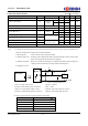
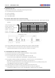
7. Electrical Characteristics
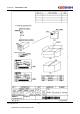
* Don't recommend Rp & Cp2
1) Rs (Vcc input series resistor) : 100 ohm ~ 470ohm
2) Cp1(Vcc-GND terminal series Condenser) : 47uF ~ 100uF
3) Rp (Vcc-Vout terminal Pullup resistor) : Optional (when using 10K ohm or more )
4) Cp2(Vcc-GNDterminal pararllel Condenser) : Optional (when using 100pF less than)
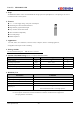
*4. B.P.F Center Frequency(fo) of each model is shown below
KKC-QM-043-2(B) 3/8
Not Support 56.9
KSM-2003 Series 37.9
KSM-2004 Series 32.7
KSM-2001 Series 40.0
KSM-2002 Series 36.7
Model NO.
B.P.F Center Frequency(㎑)
100㎷p-p under the measuring circuit specified in drawing(8-2,3)
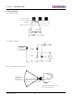
4) Application Circuit
fluorescence lamp without high frequency lightning
3) Standard transmitter : Burst wave indicated in drawing(8-1) of standard transmitter shall be arranged to
under the conditions below against the standard transmitter
1) Measuring place : Indoor without extreme reflection of light
2) Ambient light source : Detecting surface illumination shall be irradiate 200±50Lux under ordinary white
Output Form Active Low Output
Note :
*3. It specifies the maximum distance between emitter and detector that the output waveform satisfies the standard(8-2,3)
800
㎲
L Level Output Pulse Width *3
T
WL
400 - 800
㎲
H Level Output Pulse Width *3
T
WH
Bust Wave = 600㎲
Period = 1.2ms
400
Vcc-0.3
30cm over the ray axis
Vcc-0.5
-
-V
L Level Output Voltage *3
V
OL
- 0.2 0.5 V
H Level Output Voltage *3
V
OH
10 - - m
12 - - m
Arrival Distance *3 L 250Lux
0˚
±30˚
940 - nm
B.P.F Center Frequency *4 fo - *4 -
㎑
Peak Wavelength *3 λp -
mA
Vcc=3V - 0.8
- 5.5 V
Current Consumption Icc
No Input
Signal
Vcc=5V - 1.0
2.0
Supply Voltage Range Vcc 2.7
[ Ta= 25℃,
Vcc= 5.0V ]
Parameter Symbol Condition Min. Typ. Max. Unit
Vcc
GND
Vcc
GND
Vout
Cp1
Rs
Receive
r
Module
Rp
micom
Cp2
Transmitter