Version 3.00.
Environment Guide Version 3.00.04 © 2010 Kofax, Inc., 15211 Laguna Canyon Road, Irvine, California 92618, U.S.A. All rights reserved. Use is subject to license terms. This product is protected by one or more of the following patents: U.S. Patents No. 4,994,926, No. 5,291,302, No. 5,459,584, No. 6,643,034, and No. 6,785,021 and Canadian Patents No. 1329852 and No. 2101327. Third-party software is copyrighted and licensed from Kofax‟s suppliers.
Environment Guide Version 3.00.04 FCC COMPLIANCE STATEMENT Information to the User NOTE: This equipment has been tested and found to comply with the limits for a Class A digital device, pursuant to Part 15 of the FCC Rules. These limits are designed to provide reasonable protection against harmful interference in a residential installation.
Environment Guide Version 3.00.04 TABLE OF CONTENTS 1. System Overview ...................................................................................................................... 7 1.1 General ............................................................................................................................ 7 2. Hardware Structure .................................................................................................................. 8 2.1 KCS Cabinets.....................
Environment Guide Version 3.00.04 7.4 How to Determine System Performance ........................................................................ 75 7.5 How to Configure Network Interface Card Teaming ....................................................... 83 8. Operating and Maintaining the KCS System .......................................................................... 90 8.1 Operation of Tandem Server System with Software Status Agent ................................. 90 8.
Environment Guide Version 3.00.04 11.12 Licenses Type 3 .................................................................................................... 122 11.13 Troubleshooting .................................................................................................... 122 12. Appendix A ........................................................................................................................... 124 13. Appendix B: KCS Approvals and Standards Conformance ...................
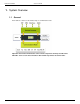
Environment Guide Version 3.00.04 1. System Overview 1.1 General Kofax delivers solutions for the widest range of communication tasks. Important! The Kofax Communication Server and its components formerly used the name TOPCALL. Some screen shots and texts in this manual may still use the former name. © Copyright Kofax, Inc. All information is subject to change without notice.
Environment Guide Version 3.00.04 2. Hardware Structure A KCS system 3xx consists of two main device types: Application Server Line Server Model 305 or 304 with Line Interfaces to PABX or PSTN 2.1 KCS Cabinets Are all intended to be 19” rack mount but can be used as desktop devices as well. Application Server Runs KCS software like TCOSS Server Operating System, Archive, and Links. The connection to the Line Server‟s/Branch Boxes is via TCP/IP-LAN (preferable dedicated).
Environment Guide Version 3.00.04 3. KCS Models 3.
Environment Guide 3.2 3.2.1 Version 3.00.
Environment Guide Operation Modes: DTMF: DID: DID Protocols: Version 3.00.04 Supported Supported Seizure Acknowledgement Delay Dial Immediate Start Wink Start Legacy Boards (TSXX) Please find the Information for these boards in TCOSS System Manual V1.13. They may be used only with Line Server Model 202. © Copyright Kofax, Inc. All information is subject to change without notice.
Environment Guide Version 3.00.04 4. Which Hard- and Software Is Supported 4.1 KCS Hardware KCS hardware is designed to the highest standards of availability and easy maintenance. It is optimized and thoroughly tested with KCS applications. Therefore optimum support and troubleshooting is guaranteed with KCS hardware. KCS takes the overall system responsibility for solutions with KCS hardware. TC/Model 300 with Windows Server 2008 is not supported. 4.1.1 4.
Environment Guide Version 3.00.04 Hyper-V feature (hardware virtualization mode) is only supported with Windows Server 2008 R2 host. Windows Server 2008 Server Core installation variant is NOT supported. 64-bit versions of Windows Server 2008: See the following section. KCS Client Applications Not supported, except TCfW Communication Server Client.
Environment Guide Version 3.00.04 KCS Performance Counters If you use Performance Counters on Windows Server 2008 64-bit version, you will have to start the service “Performance Counter DLL Host” and set it to start automatically. See section 8.2 KCS Performance Counters for details. The tool TC/PerfLog supports only Mode-0 on Windows Server 2008 64-bit version. For details see the TC/PerfLog Technical Manual.
Environment Guide 4.4 Version 3.00.04 Third-Party Hardware Support 4.4.1 General The market increasingly requests support of standard server hardware. Many companies have strong partnerships with hardware vendors or internal policies regarding hardware to use. Typically those customers have maintenance agreements with hardware vendors like IBM, Compaq or HP who take responsibility for all their hardware.
Environment Guide Version 3.00.04 For further information about special hardware requirements regarding different KCS server applications refer to the product related requirement list at the end of this chapter. 4.4.4 Microsoft Hardware Compatibility List Now it is possible to use third-party hardware instead of Kofax certified models even these servers have to meet all of the Microsoft Windows Logo requirements.
Environment Guide Version 3.00.04 Step one Enter the exact model description like mentioned before, E.g.: IBM “xSeries server 342 Model 86692RX”. Select “System/Server” from the types section. This is important because otherwise you will get a lot of entries which make it more difficult to find the one you want to use. Step two The output should look like this: If the machine you are looking for is the IBM servers xSeries 342 (DUAL 1.133 GHz). Click on the second entry in the list.
Environment Guide Version 3.00.04 Click on the second from top in the list. The information in detail: As you can see there is the note “Server Design Guide 2.0 Compliant” in the Windows 2000 line, which means that this machine has a valid Microsoft hardware compatibility listing. This is what is necessary to be KCS compliant. There are three possible levels of Microsoft support for a specific product: All other logos do not lead to a Microsoft hardware complaint machine supported by KCS.
Environment Guide Version 3.00.04 The server can be found in the last line. Detailed information: © Copyright Kofax, Inc. All information is subject to change without notice.
Environment Guide Version 3.00.04 Example 2 DELL PowerEdge 2550 server with dual PIII 1.4 GHz processor: The server can be found in the last line. Detailed information: 4.4.5 Prerequisites The fulfillment of the criteria of all previous steps (Minimum Requirements, Microsoft Hardware Compatibility List) is the base for a proper cooperation between third-party hardware, operating system (Windows Server 2003 and Windows Server 2008) and KCS server software.
Environment Guide Version 3.00.04 Note: In case of hardware related problems, Kofax reserves the right to demand the use of KCS server hardware, in order to solve above mentioned problems. E.g.: blue screens, Dr. Watson, Network 4.4.
Environment Guide 4.4.8 Version 3.00.04 Known Issues on Outdated Third-Party Hardware If running up-to-date KCS applications under modern operating systems like Windows 2008 on outdated hardware which is not listed on Microsoft HCL, it must be taken into account that there is a higher risk that any issues may occur during KCS installation and operation. This chapter summarizes problems and hardware related issues which have already been observed on particular outdated hardware.
Environment Guide Version 3.00.04 5. KCS in Virtual Environment 5.1 Overview on Virtualization Nowadays in the IT business there is a strong trend called virtualization. It means that applications are moved from a couple of physical, often underutilized servers towards virtual environments running on a single or a few very powerful servers (hosts) that may host a couple of virtual machines, in the context of which different (guest) operation systems (OS) may be running.
Environment Guide Version 3.00.04 There are many professional tools available today to help customers to collect performance and workload characteristics of the applications to be virtualized. For example, VMware offers its Capacity Planner service through their partners to help customers understand their virtualization opportunities.
Environment Guide Version 3.00.04 If such an event occurs, the system administrator should allocate more resources to the particular VM and the problem would be solved. It is the role of the administrator to observe virtualized servers and tune them for optimal performance. KCS does not prescribe exact resource requirements for non real-time applications. 5.2.2 Requirements VMware Requirements 1.) The supported virtualization platform is the VMware ESX Server 3.01 or later 2.
Environment Guide Version 3.00.04 b.) Minimum RAM in MByte Can be accomplished by the ESX VI client, refer to the following example: 5.) TCOSS file structure must be stored on the dedicated SAN VMFS volume (in order to minimize high contention operation while sharing the same volume with a lot of other VMs). 6.) Keep at least 100MByte free room on the VMFS volume (dedicated for the TCOSS file structure) (During the formatting of the TCOSS File structure, enter the size in MByte that is by ca.
Environment Guide Version 3.00.04 The reason for doing so is to be able to test the disk access to this volume using the dedicated TcDiskTest tool. If this recommendation is not fulfilled, it will be not possible to test actual disk throughput with the dedicated TcDisktest tool afterwards 7.) 1 virtual CPU (VCPU) should be used. 8.) All other KCS applications connecting to the TCOSS must be run in separate VM(s).
Environment Guide 5.2.4 Version 3.00.04 Resources Estimation for Existing Customers During the virtualization planning, the existing customers would usually use any of specialized capacity planning tools (Platespin PowerRecon, VMware Capacity Planner, …) to collect performance data of their physical servers (the usage of them is out of scope of this document) and then plan the deployment of their virtual infrastructure.
Environment Guide Version 3.00.04 Diskperf –Y After the measurement has been finished, consider especially following counters: 1. a.) Number of processors (n) b.) Processor(s) total utilization in % (u) along with information on CPU model and frequency (f) (e.g., Pentium IV 1500MHz) c.
Environment Guide Version 3.00.04 3. All received documents are fetched and printed by the IPPrinter (running in the separate VM) to the Windows printer server Following resource estimation and key performance indicators table consists of three parts: 1. Required granted resources are those that must be permanently allocated on the ESX Server for the TCOSS VM. The ESX Server itself guarantees that these resources are available 2.
Environment Guide Used abbreviations Version 3.00.04 Explanation Performance Object Performance Counter RTTls1 RTTFoIP Instance Name L.XY Round-trip-time between TCOSS Links Avg. Packet-Ack Time ms TCOSS and LS1 Peak Packet-Ack Time ms servers/TC/FoIP Servers RTTprim-sec Round-trip-time between TCOSS Links Avg.
Environment Guide Version 3.00.04 Following resource estimation and key performance indicators table was measured under similar circumstances as the TCOSS resource estimation table in previous chapter, with the following differences: 1. Single TCOSS instance was used and the TC/FoIP process was running on the same VM 2.
Environment Guide Version 3.00.
Environment Guide Version 3.00.04 In the panel Resources of the Virtual machine Properties dialog: 5.3.2 Memory Amount of the memory allocated for the particular VM can be configured via the Hardware panel of the Virtual machine Properties (configured memory can be changed only if the VM is powered off): 34 © Copyright Kofax, Inc. All information is subject to change without notice.
Environment Guide Version 3.00.04 Granted Memory resource (memory reservation) can be allocated using the shares method or explicitly grant enough memory for the VM in the Resources panel: The configured RAM in the hardware panel is the amount of memory allocated for the particular VM by the ESX server, but not granted to it exclusively (it could be e.g. shared with the other VMs). Memory exclusively granted to the VM is specified in the Resources panel (as memory reservation).
Environment Guide Version 3.00.04 One of the main reasons for having two distinct RAM setting for the VM is the swap file size estimation for the particular VM, consider examples: 1. If configured memory (Hardware panel) equals to 512 MByte, but reserved memory equals 0, then the size of the swap file would be 512 MByte 2.
Environment Guide Version 3.00.04 Note that it is recommended for the TCOSS file structure to be allocated on a separate VMFS volume (in order to minimize contention with the other VMs). 5.3.4 Network Similar to the disk resources, there is no possibility to allocate required network bandwidth for a particular VM. On the ESX host there is only a possibility to configure so called network traffic shaping, that performs the opposite, i.e.
Environment Guide Version 3.00.04 2. Allocate enough CPU bandwidth for the VM kernel 5.4 Virtualized Operation This chapter provides information how to check the availability of particular resources prior to the and during the operation of the KCS platform on the ESX server. 5.4.1 Checking CPU and Memory Requirements As the requested resources must be granted for the particular VM running real-time applications (e.g.
Environment Guide Version 3.00.04 or alternatively export the performance data from the VI client to the Excel sheet and consider afterwards: 2. Observe VI‟s counter CPU ready and CPU wait: a.) CPU ready is the amount of time in ms (since last performance query – 20 seconds by default) the VM was ready to work but it was not scheduled by the ESX server. In other words, the higher CPU ready value is, the fewer CPU resources the VM gets b.
Environment Guide Version 3.00.04 3. Start the test workload for an hour and check the Memory granted, Memory consumed and Memory active counters in the VI client (may be also exported as Excel sheet): Memory granted is the amount of memory that has been reserved for the particular VM by the ESX server. Memory consumed is the memory the VM is really consuming, Memory shared is memory that has been saved due to memory sharing among VMs. Roughly said, Memory consumed = Memory granted - Memory shared.
Environment Guide Version 3.00.04 Memory active is the amount of memory that the VM is actively using, based on the current VM activity, applications running there etc. (on the other hand, Memory consumed is the memory the VM is “occupying” on the ESX server, despite of the current VM activity). As a rule of the thumb it can be said that memory active should always be lower than memory consumed for the proper VM‟s operation without a lot of RAM swapping.
Environment Guide Version 3.00.04 Copy the TcDiskTest.exe and TClib32.dll to any directory on the TCOSS server (tclib32.dll is only necessary if there has been no KCS installation before, if the TCOSS has already been installed the TCLIB32.DLL is already available there).
Environment Guide Version 3.00.04 In order to see the performance counters provided by TcDiskTest, start Windows performance monitor, add performance object “TcDiskTest” and all three counters: Start collecting these counters for a period of time: The best indication for the suitability of the particular VM for the TCOSS operation are the Avg.
Environment Guide Version 3.00.04 Setting of the Test Cycle Parameter With a higher test cycle value (e.g. 1000ms) the TcDiskTest tool would make fewer disk IOs than a fully utilized TCOSS server, but anyway it may still detect disk bottleneck in the virtual environment if the disk resource is full overloaded. For example, starting TcDiskTest with the command line TcDiskTest -p1000 -t360000 -dd would produce around 4kByte/s transfer data towards the disk, which is much more less than TCOSS would.
Environment Guide Version 3.00.04 Further useful counter is the Write Queue Length Peak (also for the TCOSS Disk performance object). Its value should be constantly lower than 16 for a good TCOSS operation, if it often shows 16 it is a good indication that there is a disk access bottleneck in the TCOSS.
Environment Guide 5.4.3 Version 3.00.04 Checking Network Latency In order to verify whether there are any network bottlenecks the easiest way is to observe so called roundtrip-time (RTT) values between particular nodes communicating through the network (note that the primarysecondary network latency is observed by the dedicated remote disk network delay counter).
Environment Guide Version 3.00.04 After some time it can be seen that the average Packet-Ack counters are within the limit (<50ms), but there are too high spikes on the peak Packet-Ack counters (reaching up to 2000ms, see blue and red graph above). This means that the network between the TCOSS and LS1 servers does not fulfill requirements (peaks must be lower than 1000ms).
Environment Guide Version 3.00.
Environment Guide 5.5 Version 3.00.04 KCS Components Supported on Virtual Environment This chapter lists KCS components supported on virtual environment. 5.5.1 Supported Client Applications TCfW Communication Server Client 5.5.2 Supported KCS Server Components 1. Administrative Tools (Group) I. KCS Monitor II. KCS License Tool – TC/LT III. TC15 Tool IV. TCPMeter V. KCS Monitoring VI. KCSBackup VII. TC/PerfLog 2. MAKETCOSS 3. TCOSS (Group) I. TCOSS II. TCOSS 01 for ASP … TCOSS 10 for ASP 4.
Environment Guide Version 3.00.04 10. SNMP Support (Group) I. SNMP Sample Scripts (Group) i. Tivoli NetView Sample Scripts ii. HP OpenView Sample Scripts II. SNMP Support Tools (Group) i. MIBMAKER ii. SNMP_CONFIG iii. MIB Files III. TCSNMP 11. TC/Probe Agent 12. TC/Report (Group)(*) I. TC/Report Report II. TC/Report Fetch III. TC/Report Request Client 13. TC/Web(*) 14. Application Interfaces and Services (Group) I. TFC II. TCSRV III. TWS IV. DocConv V.
Environment Guide 9) Version 3.00.04 Alternatively PDF conversion done with Acrobat Reader 7.0.7 (no script) Used servers 1. Physical machine Mod. 300 KCS Mod. 300 – TA11 main board, 512 MB RAM, 1 x 2,8 GHz Xeon processor, SCA hard disk 2. VMware session under ESX server - version 3.0.1 – Build 32039 VMware session 512 MB RAM, 1 x 2,8 GHz Xeon processor 3. VMware session under (GSX) server - version 1.0.
Environment Guide Version 3.00.04 Test results Pages/ hour - application not started by TCDCLink VM WS VM GSX VM ESX Mod. 300 Acrobat Standard 7.x script PDF 570 PDF 4 pages % pages % Acrobat Reader 7.
Environment Guide Version 3.00.04 The supported host operating system is Windows Server 2008 R2. It is recommended to use Microsoft Hyper-V Server 2008 R2 (http://www.microsoft.com/hyper-v-server/en/us/default.aspx) instead of a normal Windows Server 2008 R2 with the server role Hyper-V. The supported guest operating systems are Windows Server 2003 and later.
Environment Guide Version 3.00.04 In the example above, one logical processor (2 GHz) is assigned to the virtual machine. The “Virtual machine reserve (percentage):” is set to 30 percent. Effectively, this machine has one processor (2 GHz) and 615 MHz are reserved for this virtual machine. The virtual machine was assigned 512 MB RAM. Supported KCS Components All KCS components supported on VMware are also supported on Hyper-V. For more information, see KCS Components Supported on Virtual Environment.
Environment Guide Version 3.00.04 Several KCS server package 7.86.00 components were installed on the host, most prominently TCOSS with 60 fax channels, connected with two LS1V2, each with 30 fax channels. In such a configuration with 60 fax channels running in parallel, test ran successfully with an average CPU usage of the virtual machine at around 13 percent. Similar configuration with 30 FoIP channels was tested successfully as well.
Environment Guide Version 3.00.04 http://kb.vmware.com/vmtnkb/search.do?cmd=displayKC&docType=kc&externalId=507&sliceId=SAL_Publi c 5.8.2 Resource Bottlenecks Caused by Virus Scanners If there are several VMs running on a particular ESX server and there are any virus scanners installed on these VMs, these virus scanners should be set up so that they wouldn‟t start their virus check cycle at the same time.
Environment Guide Version 3.00.04 6. IPv6 Protocol 6.1 Introduction IPv6 protocol is the successor of the well-known IPv4 protocol which is being used in the Internet nowadays. It was defined in December 1998 by IETF in the specification RFC 2460. The necessity for better IP protocol is driven especially by the lack of address space provided by IPv4 addressing scheme.
Environment Guide 6.2.2 Version 3.00.04 IPv6 Address Types There are three types of IPv6 addresses: unicast, multicast and anycast. Unicast IPv6 address is an address for a single interface. Multicast IPv6 address is an address for a set of interfaces and a packet sent to such an address will be delivered to all interfaces identified by this address. Anycast IPv6 address is also an address for a set of interfaces, but a packet sent to such an address is delivered to one of these interfaces. 6.2.
Environment Guide Version 3.00.04 Having received the IPv6 address prefix from the router, IPv6 host generates its interface identifier in order to generate the full IPv6 address.
Environment Guide Version 3.00.04 The interface has the following IPv6 addresses assigned: 1.
Environment Guide 6.4.3 Version 3.00.04 Scenario 3: IPv6 only Network Having started to implement the Scenario 1 or 2, the final goal is clearly the IPv6 only network. All nodes in the networks which could be IPv6 enabled communicate via IPv6 only but they can„t reach IPv4 nodes which could not be equipped with IPv6 for any reason (old applications not supporting IPv6, old OS, running on the old hardware etc).
Environment Guide Version 3.00.04 KCSCore IPV6/IPV4 TC/LINK Server IPV6/IPV4 IPV6/IPV4 Network LS1 IPV4 EmailServer IPV4 KCSClient IPV4 KCSClient IPV6 In this way administrators may perform the migration towards IPv6 step by step, for example starting by IPv6 enabling of the servers, and then adding IPv6 for related client applications. 6.5.
Environment Guide Version 3.00.04 KCSCore IPV6 TC/LINK Server IPV6 IPV6 Main-Network IPV4 Sub-Network NAT-PT Translation EmailServer IPV6 LS1 IPV4 KCSClient IPV6 KCSClient IPV6 There are the following requirements to implement NAT-PT on a Cisco router in order to integrate KCS IPv6-only Windows applications with KCS IPv4-only hardware boxes: 1.
Environment Guide Version 3.00.04 1. In order to send a packet to the LS1, KCS core has to send it to its IPv6 “proxy address” FD96::1 (the IPv6 network must take care that this packet would be routed to the appropriate NAT-PT router‟s interface) 2. The router recognizes the prefix fd96::/96 in the packet‟s destination address and executes the NAT-PT translation for this packet (due to NAT-PT prefix configuration) 3.
Environment Guide Version 3.00.04 ipv6 nat v6v4 source fd96:eb5f:7508:5760:204:23ff:feac:4172 172.20.148.53 ipv6 nat prefix FD96::/96 ! Cisco router 28xx configuration using dynamic IPv4-mapped NAT-PT: This configuration allows each IPv6 only host to talk with any of the IPv4 only hosts by: 1. Defining the pool/range of IPv4 addresses as IPv4 “proxy” addresses for IPv6 hosts (in the example below 172.20.148.53 – 172.20.148.62 with the prefix length 24, which corresponds with IPv4 mask 255.255.255.0) 2.
Environment Guide Version 3.00.04 1. NAT-PT translation is not supported in Cisco Express Forwarding (CEF). The CEF must be disabled by the command no ipv6 cef (see examples above). 2. It may be necessary to disable IPv6 redirects on the IPv6 interface taking part in the NAT-PT by the command no ipv6 redirects (see examples above). The reason for this is unclear.
Environment Guide © Copyright Kofax, Inc. All information is subject to change without notice. Version 3.00.
Environment Guide Version 3.00.04 7. Configuration Examples 7.1 How to Configure a KCS Solution The examples on the following pages show typical KCS hardware configurations. The optimum configuration for every single customer is planned by trained Kofax sales and technical professionals together with customer representatives. 68 © Copyright Kofax, Inc. All information is subject to change without notice.
Environment Guide 7.1.1 Version 3.00.
Environment Guide 7.1.2 Version 3.00.04 FAX + VOICE via ISDN (BRI or PRI) line; FAX via Analogue (T/R or E&M) Line Entry Solution with Application Server Model 301 and KCS Models 304 and 305 7.1.3 TELEX and Host Connections Solution with Application Server Model 300 and KCS Model 202 LAN 70 © Copyright Kofax, Inc. All information is subject to change without notice.
Environment Guide 7.1.4 Version 3.00.04 KCS Tandem Configuration Solution with 2 Application Servers and KCS Line Servers © Copyright Kofax, Inc. All information is subject to change without notice.
Environment Guide 72 Version 3.00.04 © Copyright Kofax, Inc. All information is subject to change without notice.
Environment Guide 7.2 Version 3.00.04 How to Estimate Bandwidth Requirements and Configuration Limits 7.2.1 Bandwidth Requirements Application Server and KCS Line Server are linked via a TCP/IP connection – either local 10/100Base/T or WAN connection in case of a BranchBox. Line Server Bandwidth Round Trip Time 30kBit/s per fax channel 70kBit/s per voice or mixed fax/voice channel 1000msec (256Byte block size) BranchBox Bandwidth Round Trip Time 30kBit/s per fax channel 1000msec max.
Environment Guide 7.2.2 Version 3.00.04 Configuration Limits Application Server LineServer/BranchBoxes: Fax/Voice channels: Number of user entries: max. 176 max. 360 260.000 Line Server Fax/voice channels: max. 32 BranchBox Fax channels: 4per LAN(10Base/T) connection (20 per Model 205 available, for more than 4 channels a separate KCS server is recommended) Maximum cable length: BRI: PRI: E&M 2wire: E&M 4wire: 7.
Environment Guide Version 3.00.04 Now transfer the TCOSS file structure via network. Remember that the only way to increase the size of the TCOSS file-structure is by copying it with TCDISK! After copying you may increase the max. File-number within the TCOSS structure and other configuration parameters with TCDISK – please see TCDISK manual for details. Line Server Optical link connection of legacy line servers has to be replaced by LAN connection with TS15/TC15.
Environment Guide Version 3.00.04 output to fax line back reception on the fax line printing of the sending copy delivery notification Client systems need power to handle the user access, e.g.
Environment Guide Version 3.00.04 The orange fields are input values. The white fields are calculated intermediate values, the result fields are blue. The message throughput of the KCS is split up into these 4 columns: Inbound fax (fax line >> KCS) Inbound link (KCS >> link >> link-specific mail system) Outbound link (link-specific mail system >> link >> KCS) Outbound fax (KCS >> fax line) The 4 columns are independent, but linked by the logic of the message flow.
Environment Guide Version 3.00.04 Adapt the 3 other input fields (“average message size in bytes”, “fax line usage per message in seconds” and “average number of pages”) if the preset values do not fit. The “average message size in bytes” is the size of the back-received documents, it only matters if the back-reception option is used. The “peak message throughput per hour” value is calculated from the “fax line usage per message in seconds” input value and the number of lines.
Environment Guide Version 3.00.04 Enable write caching on the disk only if the KCS is connected to an uninterruptible power supply (UPS). Otherwise power failures may leave the TCOSS file system in an inconsistent state. Write caching on the disk improves the speed of random writes considerably, for a rough estimate take a factor of 2. HW RAID Configurations For increased disk throughput use a HW RAID configuration in combination with battery-backed write cache on the disk controller.
Environment Guide Version 3.00.04 Example: A HW RAID 1+0 using a RAID controller with 512MB Battery-Backed Write Cache (BBWC) option and 8 hard disks with individual access times of 7 ms gives random write throughput figures of about 2000 writes per second. Each disk would allow 140 writes per second, so the RAID 1+0 is about 14 times faster, of which a factor of 4 can be attributed to the striping and a factor of 3.5 to the optimizations done by the RAID controller.
Environment Guide Version 3.00.04 The above measurement was run on a system with hard disk write caching enabled. The first value reported is a bit higher as the cache fills up, this value can be discarded. With hard disk write caching disabled the same system showed these throughput numbers: Remember that hard disk write caching requires an uninterruptible power supply (UPS). Also do not forget to clean up the test file “C:TcDiskTest.bin” or “D:TcDiskTest.bin” after finishing the throughput tests. 7.4.
Environment Guide Version 3.00.04 Text message (4kB): Message with 50kB attachment: GW message to KCS: 17000messages/hour 7200 messages/hour Text message (4kB): Text message (4kB) with 50kB attachment Same, sent to FAX user Notification from GW Tested with Model 2xx. 14400messages/hour 7200 messages/hour 275 messages/hour 27000 /hour TC/LINK-LN: Test Description Pages/hour Messages/hour sec/msg T1. Text msg 1P Mail -> TC 19047,6 19047,6 0,19 T2. TCDC Word 1P Mail -> TC 486,3 486,3 7,40 T3.
Environment Guide Version 3.00.04 TC/LINK-SC: Test Description Time measured (ms) Messages/hour T1. Text msg 1P Mail -> TC 4000 9000,0 T2. TCDC Word 1P Mail -> TC 75000 480,0 T3. TCDC Word 100 P Mail -> TC 320000 112,5 T5. Bin Att (105K) Mail -> TC 70000 514,3 T6. Bin Att (1.14M) Mail -> TC 290000 124,1 T7. FAX TIF 1P TC -> Mail 18000 2000,0 T8. FAX TCI 1P TC -> Mail 15000 2400,0 T9. Text msg 1P TC -> Mail 13000 2769,2 T10. Bin Att (105K) TC -> Mail 13000 2769,2 T11. Bin Att (1.
Environment Guide Version 3.00.04 By NIC teaming more than one physical NIC to a logical NIC, high availability of a TCOSS server is maximized. Even if one NIC (or cables) fails, the network connection does not cease and continues to operate on other NICs. 7.5.1 NIC Teaming with Intel Advanced Networking Services (ANS) If a computer has at least one Intel NIC, the NIC teaming can be configured with Intel ANS. For download and installation see http://www.intel.com/support/network/sb/cs-009747.htm.
Environment Guide Version 3.00.04 Click New Team to start a wizard that guides you through the process of creating a new team. Type a name. Select team members: Select team type: © Copyright Kofax, Inc. All information is subject to change without notice.
Environment Guide Version 3.00.04 When you finish the wizard, you can view and change the properties of the team: Network connections after defining a NIC team: 7.5.2 NIC Teaming with HP Networking Configuration Utility (NCU) On computers with HP network interface cards, you can define teaming with the HP Network Configuration Utility (NCU). This tool can be found from HP webpage: http://search.hp.com/query.
Environment Guide Version 3.00.04 The original state of network connections without NIC teaming: Start HP NCU. Select the members of NIC team. Click Team. Edit the properties of the team. Click OK, then click Save. The network connections will change: © Copyright Kofax, Inc. All information is subject to change without notice.
Environment Guide Version 3.00.04 If you need to configure the IP settings manually, open the local area connection properties of defined team. Note: Close HP NCU before opening properties. 88 © Copyright Kofax, Inc. All information is subject to change without notice.
Environment Guide Version 3.00.04 To display the state of team, open NCU, select the team and click Properties. © Copyright Kofax, Inc. All information is subject to change without notice.
Environment Guide Version 3.00.04 8. Operating and Maintaining the KCS System 8.1 Operation of Tandem Server System with Software Status Agent In general operation of the Software Status Agent is similar to the Status Box. For details see user manuals for TCMON. 8.1.1 Recommended Power On/Off Sequence for Tandem Server If possible, the following sequence should be used if a model 22x must be switched off or on manually. Turning off a TC means stopping TCOSS.
Environment Guide Version 3.00.04 2 ISDN BRI Channels running on second LS1 (Booted by Primary, Secondary can take over) Test 1: Primary Server Off – Secondary Server Takes Over The system is running in normal mode. The Primary Server has the control. The primary server gets powered off.
Environment Guide Version 3.00.04 Test 3: Secondary Server Standalone – Primary Server comes back and boots from Secondary’s disk This is the same situation as in Test 3 with the difference that the Primary Server cannot access its KCS File Structure and has to boot from the Secondary Servers disk.
Environment Guide Version 3.00.04 Connection no LAN signal detected Left LED off Right LED off Example 10 Mbps LAN connection blinking green 1 sec on/off flickering yellow to indicate activity on LAN 100 Mbps LAN connection steadily green flickering yellow to indicate activity on LAN Description of TC23/TC24/TC26 LEDs LED status Left off TC23.
Environment Guide Version 3.00.04 Menu Pressing mode at any time (except directly after booting) brings up the menu. Pressing mode again cycles through the menu items, pressing Set selects a menu item. Pressing mode after the last menu item returns to standard display.
Environment Guide Version 3.00.04 For IP address and gateway address, the setting starts at the tenth position of the first quad. Pressing set changes the value, pressing mode moves onto the next value. After the last position, you are asked to press set to confirm. If you press mode instead, the setting is not changed. For the net mask, pressing set adds one-bits to the net mask, until mode is pressed. Again, you are asked to confirm the change. Changes apply only after MODEL 305 is rebooted.
Environment Guide CHANNEL Version 3.00.04 Number of the logical channel that caused the error in HEX-format. If no channel number appears, the error was generated from a module which is used from all channels. Name of software module that caused the error (e.g. TAM, TOS, KK99 …).
Environment Guide Version 3.00.04 4) If the KCS system is still accessible you should check all system error messages (ATE???? Files in system folder) to locate the cause of the error. 5) In case you cannot access the KCS system start the event viewer of the NT administrative tools and check the application event log. 6) Try to solve the problem according to the error message description. 7) If you cannot solve the problem yourself report the error message to your KCS engineer. 8.1.
Environment Guide Version 3.00.
Environment Guide Version 3.00.04 58_009_NAME=TCSI 58_009_HELP=TCSI 60_009_NAME=TCSI 60_009_HELP=TCSI 8.2.
Environment Guide Version 3.00.04 Last Counter Last Help DWORD DWORD - PerfIniFile STRING “TcLibPerf.ini” the “Counters” and “Help” values of the system located here: “HKLM\SOFTWARE\Microsoft\Windows NT\CurrentVersion\Perflib\” The “First Counter” value is the offset to calculate the absolute counter index from the relative counter index in the counter ini-file.
Environment Guide Version 3.00.04 1) Stop all performance gathering applications like Perfmon, also remote instances. If TC/SNMP is installed, stop also the SNMP service. 2) Stop all KCS applications by stopping TCSRV and also close TC/Mon; -> after that tclib32.dll should not be loaded any more by any application. You can check that e.g. with the tool “Process Explorer”. Local Perfmon instances are shown as process “mmc.exe”, remote connections use (on Windows 2003) the process “svchost.exe”. 8.2.
Environment Guide Version 3.00.04 15) Version and date of tclib32.dll in c:\topcall\shared 16) Counter initialization file 17) Trace files - location c:\tcoss\trace; from all KCS applications and from Perfmon (“TCLIBPERFx.trc”) 18) Registry export from: HKLM\SYSTEM\CurrentControlSet\Services\TcLib\Performance HKLM\SOFTWARE\Microsoft\Windows NT\CurrentVersion\Perflib HKLM\SOFTWARE\TOPCALL 8.
Environment Guide Version 3.00.04 Registry value Description HKLM\Software\Microsoft\Windows\ Create mini dumps Windows Error Reporting\LocalDumps\DumpType=1 HKLM\Software\Microsoft\Windows\ Folder for mini dump files Windows Error Reporting\LocalDumps\DumpFolder= (holds the last 10 dumps) “C:\TOPCALL\SHARED\CrashDumps” In addition, if Enable User-Mode Dumps is selected, the startup type of the Windows Error Reporting service will be set from Manual to Automatic. © Copyright Kofax, Inc.
Environment Guide Version 3.00.04 9. Security Strategy No doubt there are no secure servers on the market but the level of security or defense measurement depend on the person who looks after the network environment. This chapter is not a security handbook. Neither is it a guarantee for a secure KCS server but it should help you to estimate the scale of raid for your system. 9.1 General By carelessness, wires often get plugged off or equipment gets switched off. (E.g.
Environment Guide Version 3.00.04 On the other hand, there are many KCS applications/modules communicating with or through third-party products (e.g. mail clients) where the TCP/UDP connectivity is not so straightforward (for example TC/Report – MS SQL server, or H.323 FoIP/VoIP integration), where one well-known TCP or UDP port is being used to establish the first connection through which further dynamic higher TCP or UDP ports to be used are agreed.
Environment Guide Version 3.00.04 TCOSS01-20 64267/tcp connection 1 and 2 (multi-TCOSS operation) 64268/tcp … 64357/tcp 64358/tcp Secondary Status Agent TCOSS 64259/tcp KCS 9.0 Y 64260/tcp Secondary Status Agent TCOSS01-20 64264/tcp Secondary TCOSS to Status Agent connection 1 and 2 KCS 9.0 Y 64265/tcp Secondary TCOSS01-20 to Status Agent connection 1 and 2 (multi-TCOSS operation) 64269/tcp 64270/tcp … 64359/tcp 64360/tcp Storage Media Server 64505/tcp KCS 9.
Environment Guide Version 3.00.04 FoIP/VoIP 1720/tcp Component IPPBX or H.323 FoIP/VoIP gateway Component H.323 with IPPBX or gateway FoIP/VoIP N N/A N N this range agreed during H.225 signaling 1024- Component exchange and the calling H.323 endpoint 65535/tcp IPPBX or H.323 with gateway FoIP/VoIP H.323/H.245 call setup (particular port from N N/A N Y establishes connection to this port) Component H.
Environment Guide Version 3.00.04 TCP ports like 57000,… ) ports See also http://support.microsoft.
Environment Guide Version 3.00.04 http://support.microsoft.
Environment Guide Version 3.00.04 Service or Device name net logon workstation Recommended start up option Auto Auto Event log messenger RPC Service Auto Auto Auto Server Auto / Manual TCP/IP NETBIOS helper Spooler service Alerter Auto SAP agent Auto TCSRV Auto Net bios interface WINS Client (TCP/IP) Manual Auto Auto Auto required for for authentication on a domain controller required for network access to shared files/printers and break messages.
Environment Guide Version 3.00.04 10. Installation Requirements 10.1 Important Safety Instructions SAVE THESE INSTRUCTIONS See APPENDIX A for other languages! Read and understand all instructions! Follow all warnings and instructions marked on the product! Do not use this product near water or in a wet basement! Do not place that product on an unstable cart, stand, or table.
Environment Guide Version 3.00.04 Unplug this product from the wall outlet and refer servicing to qualified service personnel under the following conditions: When the power supply cord or plug is damaged or frayed. If liquid has been spilled into the product. If the product has been exposed to rain or water. If the product does not operate normally by following the operating instructions.
Environment Guide Version 3.00.04 Side distance Rear distance Attention: Leaf 1HE of 19” rack free above the RAID cabinet! (For cooling purposes!) 10.3 Rack Mounting The KCS Model‟s 305 may be mounted in any 19” standard rack with cooling and minimum depth of 600mm. One KCS Model 305 requires 1HE (45mm / 1 ¾”) height. Model 305, since it is quite small and light, is not intended to be mounted on sliding rails – simply screw it with the front screws to the vertical rack rails. © Copyright Kofax, Inc.
Environment Guide Version 3.00.04 10.4 Operating Temperature Temperature: Min. +10°C / 50°F Max. +40°C / 104°F, RAID cabinet max. +32°C / 90°F The KCS system works on a desktop installation without any additional cooling in a typical office environment. Non desktop installations require proper mounting to provide airflow and prevent overheating. In case of doubt external ventilation should be provided (e.g.: rack-mounted). 10.
Environment Guide Version 3.00.04 Cable Form The cable has to be in one piece from end to end. It is not allowed to put more pieces together. Cables to ISDN, Analogue or E&M devices must be shielded and have to be equipped with ferrite cores provided by Kofax. The cores must be mounted as near as possible to the KCS Server. The cable has to be wound around the core twice (turns as far apart as possible). Cabling has to be 26 AWG (0,13mm²) size as a minimum.
Environment Guide Version 3.00.04 11. KCS Licensing 11.1 Licensing General KCS software is protected by license keys. These keys are maintained in the KCS server. At the time of installation the KCS engineer enters all required licenses. Licenses: A license key is required in order to enable a specified number of instances of a program. Only licenses for TC/GATE are entered directly via TC/GATE, all other licenses are entered using the KCS Licensing Tool, LICENCES.EXE. 11.
Environment Guide Version 3.00.04 11.4 Link Licensing 11.4.1 Per User Link Licensing Some TC/Links are licensed per user: TC/LINK-LN TC/LINK-MX TC/LINK-GW 11.4.2 Special Link Licensing TC/Link-SC and TC/Link-AC use a special form of per instance Licensing. First of all you need a license for every workstation on which a TC/Link-SC is running. Then, for every 3 instances of TC/Link-SC which are running on the same workstation, you need one TC/Link-SC license.
Environment Guide 11.4.4 Version 3.00.04 Image Licenses Image licenses are licenses required for image conversion done by the links. The image types needing a license are: Postscript PCL GIF PDF Every time a TC/Link does file conversion this action is registered on TCOSS. If a registration is already used for the workstation hosting the TC/Link, it will be used again. If there is no registration available, the conversion will not be done. 11.4.
Environment Guide Version 3.00.04 The VOICE IP PORT license allows the use of voice channels with Cisco. The effect of missing channel licenses is – if there are more channels configured than licenses present, TCOSS starts in restricted mode. Important: Channel licenses are exclusively consumed by channels on TCOSS, no Link server or TFC application uses up a channel. 11.5.
Environment Guide Version 3.00.04 11.9 Test Mode Test mode allows operation of a KCS system without appropriate license keys for a limited period of time. If the “Switch to Testmode” button is clicked, TCOSS will switch into the licensing test mode. This mode disables all license checks for a test phase of 7 days. The test phase is followed by a recovery phase of 30 days with regular license checking. Within this recovery phase it is not possible to switch TCOSS into the test mode again.
Environment Guide Version 3.00.04 11.
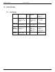
Environment Guide Version 3.00.04 11.12 Licenses Type 3 Short Name TandemAgent Least Cost EMailReader VoiceAttend TC/SNMP TC/FIREWALL TC/Probe TC/PLAYER TC/TDLIT Fax Channel VoiceChannel Fax Voice VoIP Channel Tlx Channel T.
Environment Guide 11.13.2 Version 3.00.04 Temporary Licenses If a temporary license is used, TCOSS generates error messages (TE???? files) 14 days before expiration. One message per day is generated. This applies for all licenses maintained by TCOSS. © Copyright Kofax, Inc. All information is subject to change without notice.
Environment Guide Version 3.00.04 12. Appendix A CONSUMER INFORMATION AND FCC REQUIREMENTS This equipment complies with Part 68 of the FCC rules. On the rear side of this equipment is a label containing, among other information, the FCC registration number and Ringer Equivalence Number (REN) for this equipment. If requested, provide this information to your telephone company.
Environment Guide Version 3.00.04 13. Appendix B: KCS Approvals and Standards Conformance 13.1 Model 305 (All Components), Model 304 and 350 13.1.1 CE Safety Standards: EN 60950:2000 CB Scheme for IEC 60950:1999 UL 1459 third edition (pending), UL94V-0 EMC Standards: EN 55022+A1, EN55024+A1, EN61000-3-2, EN61000-3-3+A1 FCC CFR47 Part 15 Class A 13.1.2 Quality Standard ISO 9001 13.1.3 ISDN Basic Rate Modem Line Interface Module TC23 TBR3 13.1.
Environment Guide Version 3.00.04 UL 1459 third edition, UL 1950 third edition, CSA C22.2 No. 950 (No. 225-M90 for RAID and Model 202), UL94V-0 EMC Emission Standards: EN 55022, CISPR 22, FCC Part 15, Subpart B, Class A, EN 50081-1:1992, 60555 Parts 2 + 3 EMC Immunity Standards: EN 50082-1:1992 13.2.2 Quality Standard ISO 9001 13.2.
Environment Guide Version 3.00.04 ETS 300 063 Direct Dialing In ETS 300 064 13.2.7 ISDN Primary Rate Line Interface Board TC34 Protocols: E1, T1/PRI DSS1 (Euro-ISDN / NET3 / ETSI) AT&T (USA) PABX QSIG (ECMA) E1: · ETS 300 011 ISDN Primary Rate User-Network Interface Layer 1 spec. and test principles · ETS 300 046 ISDN Primary Rate Access - safety and protection T1: · ANSI T1.403 Network-to-Customer Installation - DS1 Metallic Interface · ANSI T1.
Environment Guide Version 3.00.04 14. Post Installation Checklist Post Installation Checklist 14.1 Goal Make sure that after a successful installation/ integration phase, the KCS system will work properly after years as well. Visit the customer 4 to 8 weeks after the installation has been finished. 14.
Environment Guide Version 3.00.04 15. Appendix C /GERMAN Safety Instructions translated to the native language of the country where the system will be installed. Sicherheitshinweise, unbedingt aufheben! Lesen Sie alle Hinweise, bis Sie sie verstehen! Befolgen Sie alle Hinweise und Warnungen am Gerät! Verwenden Sie das Gerät nicht in der Nähe von Wasser oder in einem feuchten Keller. Stellen Sie das Gerät nicht auf einen Wagen, Ständer oder Tisch, wenn diese keine ausreichende Stabilität aufweisen.
Environment Guide Version 3.00.04 Wenn das Gerät trotz Befolgen der Bedienungsanleitung (System Manual) nicht ordnungsgemäß funktioniert, benützen Sie nur jene Einstellmöglichkeiten, die in der Bedienungsanleitung angeführt sind, denn unsachgemäße Einstellung anderer Kontrollmöglichkeiten kann zur Zerstörung des Gerätes führen und verursacht oftmals einen unnötig hohen Aufwand für qualifiziertes Servicepersonal, um das Gerät wieder in Gang zu setzen.