Installation Commercial Mobile Generator Sets Model: 10ERG 13ERG 15ERG TP-6335 9/04
Table of Contents Safety Precautions and Instructions . . . . . . . . . . . . . . . . . . . . . . . . . . . . . . . . . . . . . . . . . . . . . . . . . . . . . . . . . I Section 1 Introduction . . . . . . . . . . . . . . . . . . . . . . . . . . . . . . . . . . . . . . . . . . . . . . . . . . . . . . . . . . . . . . . . . . . . . 1.1 Installation Standards . . . . . . . . . . . . . . . . . . . . . . . . . . . . . . . . . . . . . . . . . . . . . . . . . . 1.2 Generator Set Specifications . . . . . . . . . .
Notes
Safety Precautions and Instructions IMPORTANT SAFETY INSTRUCTIONS. Electromechanical equipment, including generator sets, transfer switches, switchgear, and accessories, can cause bodily harm and pose life-threatening danger when improperly installed, operated, or maintained. To prevent accidents be aware of potential dangers and act safely. Read and follow all safety precautions and instructions. SAVE THESE INSTRUCTIONS.
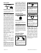
Battery short circuits. Explosion can cause severe injury or death. Short circuits can cause bodily injury and/or equipment damage. Disconnect the battery before generator set installation or maintenance. Remove all jewelry before servicing the equipment. Use tools with insulated handles. Remove the negative (--) lead first when disconnecting the battery. Reconnect the negative (--) lead last when reconnecting the battery.
Fuel System WARNING Explosive fuel vapors. Can cause severe injury or death. Use extreme care when handling, storing, and using fuels. The fuel system. Explosive fuel vapors can cause severe injury or death. Vaporized fuels are highly explosive. Use extreme care when handling and storing fuels. Store fuels in a well-ventilated area away from spark-producing equipment and out of the reach of children.
Welding the generator set. Can cause severe electrical equipment damage. Before welding the generator set perform the following steps: (1) Remove the battery cables, negative (--) lead first. (2) Disconnect all engine electronic control module (ECM) connectors. (3) Disconnect all generator set controller and voltage regulator circuit board connectors. (4) Disconnect the engine batterycharging alternator connections. (5) Attach the weld ground connection close to the weld location. Short circuits.
Notice WARNING NOTICE Airborne particles. Can cause severe blindness. This generator set has been rewired from its nameplate voltage to injury or Wear protective goggles and clothing when using power tools, hand tools, or compressed air. 246242 NOTICE Tightening the hardware. Flying projectiles can cause severe injury or death. Loose hardware can cause the hardware or pulley to release from the generator set engine and can cause personal injury.
Notes VI Safety Precautions and Instructions TP-6335 9/04
Section 1 Introduction All information in this publication represents data available at the time of print. Kohler Co. reserves the right to change this literature and the products represented without incurring obligation. The safe and successful operation of a mobile power system depends primarily on the installation. Use this manual as a guide for installing the mobile generator set. Refer to the operation manual for operating instructions. 1.
Notes 2 Introduction TP-6335 9/04
Section 2 Location and Mounting 2.1 General Considerations 2.3 Vehicle-Floor Mounting Consider the following items concerning the generator set and Section 2.2 for the proposed location. Install the Kohler mobile generator set on an open vehicle’s floor or truck bed. Follow the guidelines below. Contact an authorized Kohler service distributor/dealer with your specific application questions. 1. Select a generator set having adequate capacity to handle the electrical load. 2.
Notes 4 Location and Mounting TP-6335 9/04
Section 3 Cooling System 3.1 Air Requirements 3.3 High Water Temperature Switch Air flow around the generator set is necessary for adequate cooling. See the current generator set specification sheet for air requirements. The air intake silencer/cleaner provides combustion air to the engine. See Figure 3-1 for allowable intake restriction. The engine/generator performance will be adversely affected if these guidelines are neglected. Follow these guidelines to optimize generator set performance.
Notes 6 Cooling System TP-6335 9/04
Section 4 Exhaust System WARNING Carbon monoxide. Can cause severe nausea, fainting, or death. The exhaust system must be leakproof and routinely inspected. Generator set operation. Carbon monoxide can cause severe nausea, fainting, or death. Carbon monoxide is an odorless, colorless, tasteless, nonirritating gas that can cause death if inhaled for even a short time. Avoid breathing exhaust fumes when working on or near the generator set.
4.1 Planning 4.3 Exhaust Piping, If Used Carefully plan the generator exhaust system to ensure a safe, quiet installation. Verify that the installation complies with all state and local requirements and applicable articles of the codes listed at the beginning of this manual. Route the exhaust piping to maintain minimum clearances and to minimize exhaust piping bends. Use a tail pipe as short as possible with as few bends as possible to reduce back pressure.
Section 5 Fuel System WARNING Explosive fuel vapors. Can cause severe injury or death. Use extreme care when handling, storing, and using fuels. The fuel system. Explosive fuel vapors can cause severe injury or death. Vaporized fuels are highly explosive. Use extreme care when handling and storing fuels. Store fuels in a well-ventilated area away from spark-producing equipment and out of the reach of children.
5.1.1 Fuel Lines 5.3 LP Gas Note: Keep fuel lines away from the exhaust system. Routing fuel lines. Take care when routing the fuel line from the fuel tank to the generator set. Keep the fuel lines as short as possible but maintain adequate clearance from the exhaust system. Route the fuel lines along the frame or undercarriage—never route the fuel lines inside the habitable area of the vehicle. Locate the fuel lines with the entry point near the fuel pump. See Section 5.4 for the fuel pump lift.
5.4 Fuel Pump Lift and Fuel Consumption See Figure 5-3 for the fuel pump lift capability. Consult the current generator set specification sheet for the generator set fuel consumption rates. Do not exceed 3 1/2 psi fuel pump pressure to the carburetor. Note: Fuel system alterations may adversely affect emissions levels. Fines resulting from higher-than-allowable emissions levels are the responsibility of the user. Figure 5-3 TP-6335 9/04 Model Fuel Pump Lift m (ft.) 10/13/15ERG 0.
Notes 12 Fuel System TP-6335 9/04
Section 6 Electrical System WARNING Hazardous voltage. Moving rotor. Can cause severe injury or death. Operate the generator set only when all guards and electrical enclosures are in place. Electrical backfeed to the utility. Hazardous backfeed voltage can cause severe injury or death. Connect the generator set to the building/campground electrical system only through an approved device and after the building/campground main switch is opened.
Note: Transfer switch. Use a triple-pole, double-throw transfer switch rated for the calculated load of the vehicle to transfer the load from one source to the other. Install a ground-fault circuit interrupter in the wiring system to protect all branch circuits. AC Vehicle Circuit Note: AC load circuit protection. Protect the AC load circuit of the generator set against overloading or short circuiting with a circuit breaker(s).
6.3 Circuit Protection The AC circuit breaker protects the generator set from extreme overload. The AC circuit breaker trips when it detects a fault in the output circuit. For application and selection information contact an authorized distributor/dealer. After correcting the fault, reset the AC circuit breaker by placing it in the ON position. Restart the unit. See an authorized service distributor/dealer for AC circuit breaker ratings.
6.3.2 lead (see Section 8). Attach stator leads 2 and 3 to L0. Circuit Breaker Installation Note: Wire material. Use stranded copper for all wiring. Use wire gauges and insulation, conductor temperature ratings, sheath stripping, conductor support and protection, conductor terminals and splices, and overcurrent protection (circuit breakers, fuses) that conform to standards and codes. Note: Wire protection.
6.4 ADC 2100 Continuous Power Mode Jumper A jumper on connector P7 on the back of the controller causes the controller to remain powered at all times. Controllers are shipped from the factory with the jumper connected. Disconnecting the jumper causes the controller to automatically power down 48 hours after the generator set shuts down. See the wiring diagram and schematic drawing in the operation manual. 4. Locate the P7 connector near the top of the controller. See Figure 6-3.
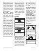
6.5 Battery and Connections WARNING Sulfuric acid in batteries. Can cause severe injury or death. Use protective goggles and clothes. Battery acid can cause permanent damage to eyes, burn skin, and eat holes in clothing. Battery gases. Explosion can cause severe injury or death. Battery gases can cause an explosion. Do not smoke or permit flames or sparks to occur near a battery at any time, particularly when it is charging. Do not dispose of a battery in a fire.
View A Using a Separate Battery for the Generator Set -- + N Battery Positive Vehicle Frame 12-Volt Battery View B Using the Same Battery as the Vehicle Engine 6.6 Remote Connection Kohler Co. offers several remote panels for connection to the generator set. Contact your local Kohlerr distributor/dealer for detailed descriptions. See Figure 6-7 for the location of the remote interface connection to the generator set junction box. Kohler Co.
Notes 20 Electrical System TP-6335 9/04
Section 7 Installation Drawing ADV-6816A-A Figure 7-1 Dimension Drawing, Gasoline Fuel System TP-6335 9/04 Installation Drawing 21
ADV-6816B-A Figure 7-2 Dimension Drawing, LP Fuel System 22 Installation Drawing TP-6335 9/04
ADV-6816C-A Figure 7-3 Dimension Drawing, Floor Template TP-6335 9/04 Installation Drawing 23
Notes 24 Installation Drawing TP-6335 9/04
Section 8 Reconnection/Adjustments WARNING Accidental starting. Can cause severe injury or death. Disconnect the battery cables before working on the generator set. Remove the negative (--) lead first when disconnecting the battery. Reconnect the negative (--) lead last when reconnecting the battery. Disabling the generator set. Accidental starting can cause severe injury or death.
8.1 Four-Lead Reconnection 100--120/200--240-Volt Configurations The following drawings illustrate the reconnection of four-lead generator sets. In all cases, conform to the National Electrical Code (NEC). The 100--120/200--240-volt configuration does not use a jumper lead. If the unit was originally wired for straight 100--120 volt, 3 wire, remove the jumper lead (see Figure 8-1 for location). Select a two-pole circuit breaker.
200--240-Volt Configurations The 200--240-volt configuration does not use a jumper lead. If the unit was originally wired for straight 100--120 volt, 3 wire, remove the jumper lead (see Figure 8-1 for location). L0 (Neutral) Ground L1 Load Side Line Side L0 GRD.
8.2.1 8.2 Advanced Digital Control (ADC 2100) The model 10/13/15ERG generator sets use the ADC 2100. The ADC 2100 uses password-protected menus for generator output adjustments and controller configuration. This section contains instructions for using the ADC’s password-protected menus to check and adjust the generator output and controller configuration. The controller configuration and generator set output are factory-set and should not require field adjustment under normal circumstances.
8.2.3 Adjusting the Voltage, Gain, and Volts/Hz After setting the system voltage, check the output voltage and adjust, if necessary, using the following procedures. Follow the instructions in Figure 8-6 to adjust the voltage, gain, and volts/Hz while the engine is running. An x in the Display column in Figure 8-6 indicates a number from 0 to 9. Use the up arrow to increase a setting or the down arrow to decrease the setting. Note: Save your settings configuration mode.
Output Voltage Adjustment Mode: Display :* Move the generator set master switch to the RUN position. The generator set engine starts and the controller display shows the engine runtime hours. x x x x Hold: Wait about 5 seconds until the display changes from runtime hours to the program version number. x. x x Press the down arrow key and then the up arrow key 3 times to enter the adjustment mode. (This is the controller “password.
Display : * Continued from Figure 8-6: To enter SAVE mode. S AV E Note: Be sure to save your settings before exiting the configuration mode. The controller reverts to the last saved settings when the master switch is moved to the OFF/RESET position. There are 3 options when the display says SAVE: Press: S AV E To return to the first parameter, coarse voltage adjustment, to check or change settings before saving. See Figure 8-6. 1 P x x To save changes. Y E S To discard changes without saving.
8.2.5 Controller Configuration The controller configuration for each generator model is set at the factory and should not normally require changes. The controller’s configuration mode allows adjustment of the system parameters listed in this section. Use the instructions in this section to check the configuration after installation and change them to match the settings shown in Figure 8-8, if necessary.
Parameter Unit’s system voltage and frequency Unit configuration Engine type Engine g data input p types yp (N magnetic (No i pick-up) i k ) Setting Uu01 Single phase, 60 Hz, 120/240 VAC Uc02 Ec03 Ed00 Ed01 Mobile generator set 10/13/15ERG All digital inputs Digital: Low coolant level and low oil pressure Analog: Low coolant temperature Digital: Low coolant level and low coolant temperature Analog: Low oil pressure Digital: Low coolant level Analog: Low coolant temperature and low oil pressure Digital:
Controller Configuration Mode (Use with Figure 8-8, Controller Parameters): Hold the Select button: Display: Move the generator set master switch to the RUN position. (The generator set engine will not start.) . Wait about 5 seconds until the display shows the program version number. (The number may be different than the one shown here.) 1 0 4 Press the down arrow key and then the up arrow key 3 times to enter the configuration mode. (This is the controller “password.
Pressing the up arrow key at the Adnc display (See Figure 8-9) puts you into the Advanced Configuration Mode. Press: or To set the engine data input type. E d 0 x To enter battery voltage selection mode. or To toggle between 12 and 24 VDC. B t 1 2 To enter communications selection mode. To set the communications parameter. or To enter SAVE mode. Go to Figure 8-11. C n 0 x S AV E Note: Shaded boxes show which number in the controller display changes when the up or down arrow key is pressed.
Notes 36 Reconnection/Adjustments TP-6335 9/04
Appendix A Generator Selection and Wattage Requirements General Wattage Requirements Appliance Loads Consider the total wattage requirements (lights, motors, appliances) when selecting a generator set, or when sizing wattage usage in which available space and construction limit the size of the generator set. Generator sets often furnish AC for appliances such as TVs, stereos, and electric water heaters.
Appendix B Abbreviations The following list contains abbreviations that may appear in this publication. A, amp ABDC AC A/D ADC adj. ADV AHWT AISI ALOP alt. Al ANSI AO API approx. AR AS ASE ASME assy. ASTM ATDC ATS auto. aux. A/V avg. AVR AWG AWM bat. BBDC BC BCA BCI BDC BHP blk. blk. htr. BMEP bps br. BTDC Btu Btu/min. C cal. CARB CB cc CCA ccw.
kg kg/cm2 kilogram kilograms per square centimeter kgm kilogram-meter kilograms per cubic meter kg/m3 kHz kilohertz kJ kilojoule km kilometer kOhm, kΩ kilo-ohm kPa kilopascal kph kilometers per hour kV kilovolt kVA kilovolt ampere kVAR kilovolt ampere reactive kW kilowatt kWh kilowatt-hour kWm kilowatt mechanical L liter LAN local area network L x W x H length by width by height lb. pound, pounds lbm/ft3 pounds mass per cubic feet LCB line circuit breaker LCD liquid crystal display ld. shd.
KOHLER CO. Kohler, Wisconsin 53044 Phone 920-565-3381, Fax 920-459-1646 For the nearest sales/service outlet in the US and Canada, phone 1-800-544-2444 KohlerPowerSystems.com TP-6335 9/04 E 2004 by Kohler Co. All rights reserved.