
Portable Generator User Manual


TP-6335 9/04 Location and Mounting 3
Section 2 Location and Mounting
2.1 General Considerations
Consider the following items concerning the generator
set and Section 2.2 for the proposed location.
1. Select a generator set having adequate capacity to
handle the electrical load.
2. Design the fuel system to prevent fuel starvation of
the main or generator set engine.
3. Ensure that the exhaust system meets all safety
requirements after installation.
4. Ensure compatibility of all electrical systems
(battery, load, and remote switch) with the vehicle’s
electrical systems.
2.2 Location
Note: This generator set is not designed for installation
in a compartment or enclosure.
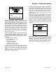
Before making final plans for locating the generator set,
ensure the following:
1. The location has sufficient room to maintain
required minimum clearances.
2. The location provides enough air flow to allow
required cooling and combustion.
3. The location can support the generator set weight.
4. The location provides ample room for routine
service of the generator set’s engine, controller,
cooling system, and fuel system components.
See the current generator set specification sheet or
Section 7 of this manual for generator set dimensions
and weights.
For angular operating limits, consult the operation
manual.
2.3 Vehicle-Floor Mounting
Install the Kohler mobile generator set on an open
vehicle’s floor or truck bed. Follow the guidelines below.
Contact an authorized Kohler service distributor/dealer
with your specific application questions.
Minimum clearance. Allow clearance for vibration and
cooling during operation. Minimum clearance for
vibration (top, front, rear, and sides) is 38 mm (1 1/2 in.).
Keep the radiator end unobstructed for proper air flow.
Additional clearance. Generator set service requires
more clearance than 38 mm (1 1/2 in.). Design the
mounting location to allow for sufficient room to easily
remove the generator set to perform major service.
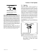
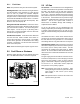
Securely fasten the generator set to avoid unwanted
movement from vibration and road shock. Attach the
generator set vibromounts directly to the vehicle’s
frame. See Figure 2-1 for vibromount installation.
1. Lock nut
2. Flat washer (7/16 x 1)
3. Generator set frame
4. Vibromount
5. Vehicle frame
6. Flat washer (13/32 x 2)
7. Screw (3/8--16 x 2--1/4)
ADV6816-
123
4
5
6
Purple (2) Engine end
White (2) Generator end
Color Mounting Location
7
Vibromount
Top View
Vibromount
Side View
Figure 2-1 Vibromount Installation