
Portable Generator User Manual


16 Electrical System TP-6335 9/04
6.3.2 Circuit Breaker Installation
Note: Wire material. Use stranded copper for all
wiring. Use wire gauges and insulation,
conductor temperature ratings, sheath stripping,
conductor support and protection, conductor
terminals and splices, and overcurrent protection
(circuit breakers, fuses) that conform to
standards and codes.
Note: Wire protection. Use rubber grommets and
cable ties as necessary to protect and secure the
wiring from sharp objects, the exhaust system,
and any moving parts.
1. Turn the generator set off and disconnect the
generator set engine starting battery, negative (--)
lead first.
2. Remove the screws and remove the access cover.
3. Remove the screws and nuts to remove the circuit
breaker cover plate. Save the mounting hardware.
4. Install the circuit breaker from the inside of the
cutout panel and mount it using the existing
screws. Position the circuit breaker with ON in the
normal upright position or to the left side. Cover the
cutout opening, if applicable, with the circuit
breaker coverplate. Use the existing screws and
nuts.
5. See Section 8 for voltage reconnection.
6. Install insulation boots over the stator lead
terminals if the kit includes insulation boots.
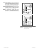
Note: See Figure 6-2 for electrical connections.
7. Make the recommended connections for the
following three reconnection systems using circuit
breakers.
Two-pole circuit breaker with a single-voltage
system (example: 120 volt, 3 wire).
Attach stator leads marked 2 and 4 to the side of the
circuit breaker marked LINE. Install the jumper
lead across the LINE side of the circuit breaker
terminals (see Section 8). Attach stator leads
1and3toL0.
Two-pole circuit breaker with a dual-voltage
system (example: 120/240 volt, 3 wire).
Attach stator leads marked 1 and 4 to the side of the
circuit breaker marked LINE. Do not use a jumper
lead (see Section 8). Attach stator leads 2 and 3 to
L0.
Single-pole circuit breaker with a
single-voltage system (example: 240 volt,
2 wire).
Attach the stator lead marked 1 to the side of the
circuit breaker marked LINE (see Section 8). Bolt
together leads 2 and 3 and tape to insulate from
ground. Attach the stator lead marked 4 to L0.
8. Connect the stator lead(s) used for neutral
connection to the L0 stud. See Figure 6-2.
9. Connect the side of the circuit breaker marked
LOAD to the transfer switch or vehicle. Attach
insulation boots to the black leads if the kit includes
insulation boots. With a single-pole circuit breaker
use one black lead L1. With a two-pole circuit
breaker use two black leads L1 and L2. Connect
the neutral white lead to the L0 stud. Connect the
equipment ground green lead to the GRD stud.
See Figure 6-2.
10. Replace the circuit breaker box access panel.
11. Reconnect the generator set engine starting
battery, negative (--) lead last.
12. For voltage adjustments, refer to the procedure in
Section 8.2.
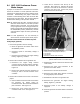
1
GM34867A-A
1. Neutral (L0) connection
2. Ground (GRD) connection
Generator-End View
2
Figure 6-2 Electrical Connections