
Installation Guide


1. Roughing-In Information
NOTICE: The floor support under the whirlpool must provide for a minimum of 3500 lbs (1588 kg).
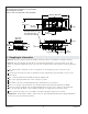
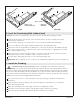
NOTICE: The areas labeled ″A″ and ″B″ are recommended installation locations for bath spouts. ″B″
applies to ceiling-mounted bath spouts only. For a list of bath spouts for this product, see the specification
sheet.
Two separate 240 V electrical services are required: one for the pump/control, and one for the
heater.
Consult local and national codes for minimum air gap requirements when installing a spout on the
faucet deck.
The overflowing bath must be filled through the bathing well.
Hot water supply should be 70% of the capacity or greater.
The fixture conforms to ANSI Standard Z124.1. All dimensions are nominal.
There is no change in measurements if connected with the drain illustrated (K-7223, K-7223M).
An access panel is required. The recommended dimensions for this access panel are 40″ (1016 mm)
Wx15″ (381 mm) H. Refer to the roughing-in diagram for suggested access panel location.
Make sure the flooring is in good condition and offers adequate support for your bath.
IMPORTANT! Verify that the subfloor is flat and level. This will help minimize the leveling adjustments
necessary for proper product performance.
A
A
B
51-7/8"
(1318 mm)
103-3/4" (2635 mm)
85" (2159 mm)
3" (76 mm)
2-7/8"
(73 mm)
1-1/2" OD
1"
(25 mm)
1"
(25 mm)
7"
(178 mm)
No change in measurements if connected with
drain illustrated. (K-7223)
Cut-out: 102-1/4" (2597 mm) x 40" (1016 mm)
41"
(1041 mm)
20-1/2"
(521 mm)
Pump/Control Access
40" (1016 mm) W x
15" (381 mm) H Min
31-13/16"
(808 mm)
26-1/2"
(673 mm)
23-11/16"
(602 mm)
1" (25 mm)
1054216-2-C 6 Kohler Co.