
Installation Guide


3. Reconnect
NOTE: Refer to the ″Before You Begin″ section for other detailed requirements for the blower motor
relocation.
At the new blower motor location, install a 1-1/2″ (3.8 cm) block (not supplied) for the new blower
motor support.
Use the blower motor as a template to mark the location of the four mounting bolts or screws.
Drill four pilot holes for the blower motor mounting screws.
Fasten the blower motor to the support board.
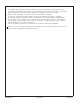
Install the check valve at the blower motor location. The check valve must be oriented vertically.
Ensure that the check valve is oriented with the flow arrow pointing away from the blower motor,
and no lower than 24” (61 cm) below the bath rim. If appropriate, reuse the screws previously
removed from the blower motor and the check valve.
Install and support PVC or other 1-1/2″ rigid piping (not supplied) between the blower motor
location and the bath air harness.
At the bath end, provide a union or other serviceable connection to the existing air harness.
Ensure that any wall holes are properly sealed as required by local building or fire codes.
Align and connect the keypad cable that is provided with this kit to the blower motor.
Route the keypad cable from the new blower motor location to the bath. Provide cable ties or other
support clips as required.
Align and connect the cable to the keypad.
4. Make Electrical Connections
WARNING: Risk of electric shock. To reduce the risk of electric shock, connect the control to a
properly grounded Ground-Fault Circuit-Interrupter (GFCI) or Residual Current Device (RCD). This
will provide additional protection against line-to-ground shock hazard.
Make electrical connections according to the Installation Guide packed with the bath.
Complete the bath installation according to the Installation Guide packed with the bath.
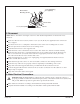
Check Valve
Screw
Screw
Blower Motor
Mounting Screws
1-1/2" (3.8 cm) Min
1-1/2" Rigid piping
(not supplied)
Kohler Co. 5 1037564-2-B