Operation Residential/Light Commercial Generator Sets Model: 24RCL Controller: RDC2 TP-6905 8/15a
California Proposition 65 WARNING Engine exhaust from this product contains chemicals known to the State of California to cause cancer, birth defects, or other reproductive harm. Product Identification Information Controller Identification Product identification numbers determine service parts. Record the product identification numbers in the spaces below immediately after unpacking the products so that the numbers are readily available for future reference.
Table of Contents Product Identification Information . . . . . . . . . . . . . . . . . . . . . . . . . . . . . . . . . . . . . . . . . . . . . . . . . . . . . . . . . . . 2 Safety Precautions and Instructions . . . . . . . . . . . . . . . . . . . . . . . . . . . . . . . . . . . . . . . . . . . . . . . . . . . . . . . . . 5 Introduction . . . . . . . . . . . . . . . . . . . . . . . . . . . . . . . . . . . . . . . . . . . . . . . . . . . . . . . . . . . . . . . . . . . . . . . . . . . . . . .
Table of Contents, continued 3.12 3.13 3.14 3.15 3.16 3.17 4 Genset Run Time Menu . . . . . . . . . . . . . . . . . . . . . . . . . . . . . . . . . . . . . . . . . . . . . . . . Genset System Menu . . . . . . . . . . . . . . . . . . . . . . . . . . . . . . . . . . . . . . . . . . . . . . . . . . ATS Status Menu . . . . . . . . . . . . . . . . . . . . . . . . . . . . . . . . . . . . . . . . . . . . . . . . . . . . . . ATS Configuration Menu . . . . . . . . . . . . . . . . . . . . . . . . . . . . . . . . .
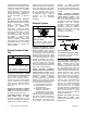
Safety Precautions and Instructions IMPORTANT SAFETY INSTRUCTIONS. Electromechanical equipment, including generator sets, transfer switches, switchgear, and accessories, can cause bodily harm and pose life-threatening danger when improperly installed, operated, or maintained. To prevent accidents be aware of potential dangers and act safely. Read and follow all safety precautions and instructions. SAVE THESE INSTRUCTIONS.
metal surface away from the battery. To avoid sparks, do not disturb the battery charger connections while the battery is charging. Always turn the battery charger off before disconnecting the battery connections. Ventilate the compartments containing batteries to prevent accumulation of explosive gases. Battery short circuits. Explosion can cause severe injury or death. Short circuits can cause bodily injury and/or equipment damage. Disconnect the battery before generator set installation or maintenance.
Propane (LPG)—Adequate ventilation is mandatory. Because propane is heavier than air, install propane gas detectors low in a room. Inspect the detectors per the manufacturer’s instructions. Natural Gas—Adequate ventilation is mandatory. Because natural gas rises, install natural gas detectors high in a room. Inspect the detectors per the manufacturer’s instructions. Gas fuel leaks. Explosive fuel vapors can cause severe injury or death. Fuel leakage can cause an explosion.
Welding on the generator set. Can cause severe electrical equipment damage. Before welding on the generator set perform the following steps: (1) Remove the battery cables, negative (--) lead first. (2) Disconnect all engine electronic control module (ECM) connectors. (3) Disconnect all generator set controller and voltage regulator circuit board connectors. (4) Disconnect the engine batterycharging alternator connections. (5) Attach the weld ground connection close to the weld location.
Introduction This manual provides operation instructions for Model 24RCL residential/light commercial generator sets equipped with the RDC2 generator set/transfer switch controller. This generator set is approved for use in stationary applications in locations served by a reliable utility power source. Have the generator set installed by an authorized Kohler distributor/dealer or service technician. Refer to the Installation Manual for installation instructions.
List of Related Literature Figure 3 identifies related literature available for the generator sets covered in this manual. Only trained and qualified personnel should install or service the generator set.
Service Assistance For professional advice on generator set power requirements and conscientious service, please contact your nearest authorized Kohler distributor or dealer. D Consult the Yellow Pages under the heading Generators—Electric. D Visit the Kohler Power Systems website at KohlerPower.com. D Look at the labels and decals on your Kohler product or review the appropriate literature or documents included with the product. D Call toll free in the US and Canada 1-800-544-2444.
Notes 12 Service Assistance TP-6905 8/15
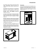
Section 1 Service Views 18 1 2 3 4 17 5 16 15 14 13 12 11 20 10 9 21 22 8 6 7 SERVICE SIDE 23 18 28 19 29 30 27 27 31 GM90230 26 25 24 ADV-8641 NON-SERVICE SIDE 1. 2. 3. 4. 5. 6. 7. 8. 9. 10. 11. 12. 13. 14. 15. 16. Oil check (dipstick) Oil fill location (on valve cover) See cooling system detail Exhaust outlet Enclosure locking key (shipping location only) Spark plugs Fuel pressure regulator Engine ECM Fuel inlet (1 in. NPT) Fuel solenoid valves (qty.
Notes 14 Section 1 Service Views TP-6905 8/15
Section 2 Generator Set Operation 2.1 Operating Area WARNING Carbon monoxide. Can cause severe fainting, or death. nausea, The exhaust system must be leakproof and routinely inspected. Carbon monoxide symptoms. Carbon monoxide can cause severe nausea, fainting, or death. Carbon monoxide is a poisonous gas present in exhaust gases. Carbon monoxide is an odorless, colorless, tasteless, nonirritating gas that can cause death if inhaled for even a short time.
WARNING Sulfuric acid in batteries. Can cause severe injury or death. Wear protective goggles and clothing. Battery acid may cause blindness and burn skin. WARNING Explosion. Can cause severe injury or death. Relays in the battery charger cause arcs or sparks. Locate the battery in a well-ventilated area. Isolate the battery charger from explosive fumes. Battery gases. Explosion can cause severe injury or death. Battery gases can cause an explosion.
Drive Belt. Check the belt condition of the water pump and battery charging alternator belt. D Check that there are no combustible materials near Exhaust System. Check for exhaust leaks and blockages. Check the silencer and piping condition and check for tight exhaust system connections. D Check that the exhaust outlet is unobstructed. Inspect the exhaust system components for cracks and corrosion (exhaust manifold, exhaust pipe, exhaust clamps, and silencer).
2.3 Exercising the Generator Set Operate the generator set without load every week or every other week for 20 minutes. Perform all of the prestart checks before starting the exercise procedure. See Section 2.5 for instructions to set the automatic exerciser. 2.4 Generator Set Operation 2.4.1 Local Starting and Stopping Start: Press the RUN button to immediately start the generator set. Stop: Press the OFF button. The engine stops.
2.4.7 Automatic Operation with Other Transfer Switches recommended exercise mode and is the factory-default exercise setting. If a Kohler Model RDT transfer switch is used, the engine start contacts from the ATS must be connected to engine start leads 3 and 4 on the generator set. The Unloaded Cycle exercise runs the engine for 20 minutes in the cycle shown in Figure 2-1 and described below.
D Communication integrity tests. J1939, RBUS, 2.5.4 D Engine speed. Engine speed is measured at low The following advanced diagnostic operation applies to RDC2 controllers with firmware versions 5.04 and higher. Ethernet, and USB are monitored for messages indicating that the controller and wiring are reliable. speed and full speed. An overspeed or underspeed condition will result in a fault condition and shutdown. D Generator output frequency and voltage.
4. The time is displayed with the hour flashing. Use the up or down arrow key to step to the current hour and am or pm setting. Note: Check the am/pm setting displayed. If pm is displayed and you need to change it to am, use the down arrow button to step down in time until the correct hour and am are displayed. 3. Press the down arrow button to step to the Genset System menu. 4. Press the Select button to enter the Genset system menu. See Figure 2-3. 5.
Status Displays Overview ----> 1.
Genset System ----> System Voltage: 240 V System Freq: 60 Hz VR Voltage Adj: 240.0V System Phase: Single System Battery: 12 V Next Exercise * Next Exercise HR:MN PM MM/DD/YY HR:MN PM MM/DD/YY See Section 2.5.8, Changing the Exercise Setting Exercise Mode: Exercise Mode: Unloaded Cycle None/Unloaded Full Sp/ Unloaded Cycle/Loaded Full SP Exercise Freq: Exercise Freq: Weekly Weekly/Every Other Week Meas.
2.6 Faults 2.6.3 Selected fault conditions are shown in Figure 2-5. Fault conditions are classified as warnings or shutdowns. If a fault occurs that is not listed in the table, contact an authorized distributor/dealer for service. When a Model RXT transfer switch is used, an ATS fault indicates that the connection to the interface board on the transfer switch has been lost. Check the connection to the ATS interface board. Note: All ECM faults are grouped under one listing in Figure 2-5. 2.6.
Fault (RDC2) Fault (OnCuer Plus) Condition AC Sens Loss AC Sensing Lost AC Sensing Lost. In Auto mode, generator Contact an authorized output AC sensing is lost. Detection begins 10 distributor/dealer for service. seconds after crank disconnect. Warning (1 sec.) Check Warning: after 1 second if no output detected after crank disconnect. Shutdwn (3 sec.) Shutdown: after 3 seconds if voltage was present and then lost. Accy PwrOver Warning Accessory Accessory Power Overload.
Fault (RDC2) Fault (OnCuer Plus) Condition Check CoolTempHigh Warning Ect Higher Than Expected 1 Coolant temperature is too high. Check coolant level. Check radiator and fans for obstruction. Contact an authorized distributor/dealer for service and provide the fault code. CoolTemp Vhi Shutdwn Ect Higher Than Expected 2 Coolant temperature is extremely high. Check coolant level. Check radiator and fans for obstruction.
Fault (RDC2) Fault (OnCuer Plus) Condition Frequency High Shutdwn High Frequency Governed frequency exceeds 110% of the system’s frequency setpoint for more than 10 seconds. Function becomes active 10 seconds after engine start (10 second inhibit). Contact an authorized distributor/dealer for service. Frequency Low Shutdwn Low Frequency Reduce the load by turning off appliances and restart the generator set.
Fault (RDC2) Fault (OnCuer Plus) Condition Check Over Crank Shutdwn Over Crank Three unsuccessful starting attempts. Check the fuel supply, spark plug, and battery. Check for loose connections. Contact an authorized distributor/dealer for service. Check the battery voltage. PrimLoopOpn Warning Primary Loop Open Ignition coil 1 voltage is below normal or there is an open circuit. PrimLoopSht Warning Primary Loop Shorted Ignition coil 1 voltage is abnormal.
2.6.5 Event Log The event log displays up to 1000 controller faults and notices, starting with the most recent event. Events are numbered 1--1000, with 1 being the most recent. Each event is displayed with the date and time of the event, the number of the event, a code to indicate whether the event was a warning ( W), shutdown (S), or informational notice ( I), the engine hours at the time of the event, and the event description.
2.7.2 ATS Control Sequence of Operation 2.7.3 Time Delays Time delays are factory-set to the values shown in Figure 2-8. An authorized distributor/dealer can adjust time delays using a personal computer and Kohlerr SiteTecht software. See Figure 2-8 for time delay settings. Normal Source Fails: Time delays described in this section operate only when the controller is connected to a Kohlerr Model RXT transfer switch. 1. The load control contact opens. 2. The engine start time delay times out. 3.
Section 3 RDC2 Controller Operation 3.1 RDC2 Generator Set/Transfer Switch Controller Model 24RCL generator sets are equipped with the RDC2 generator set/transfer switch controller. The RDC2 controls the following power system components: 3.2 Controls and Indicators Figure 3-1 illustrates the keypad, display, and indicators on the controller’s user interface.
3.2.1 Controller Keypad The Run, Off, and Auto buttons control the generator set as described in Figure 3-2. Use the Select, Up arrow, and Down arrow buttons to navigate through the menus and change settings, if necessary. See Section 2.4 for operation instructions. 3.2.2 LED Indicators LEDs above the RUN, OFF, and AUTO buttons indicate the mode of operation as shown in Figure 3-2. The RDC2 controller also has a set of power system LEDs below the pushbuttons.
3.2.3 LCD Display The controller is equipped with a two-line x 16 character backlit liquid crystal diode (LCD) display with adjustable contrast. When the generator is running, the controller automatically scrolls through the displays shown in Figure 3-4. When the system is in AUTO, the LCD display scrolls through the status messages shown in Figure 3-5. When a fault or warning condition exists, the controller will show the corresponding message. See Section 2.
3.3 Controller Power The RDC2 controller is powered by the generator set engine starting battery and the built-in battery charger. Note: To disconnect controller power, disconnect the battery and the utility power to the generator set. If controller power is disconnected and reconnected, you will be prompted to set the time, date, and exerciser. The first setting will flash. Press the Up and Down arrow buttons to change the setting. Press Select to save the setting and move on to the next.
Changing Settings on the RDC2 Controller 1. Press the Select button to enter the main menu. Press: Display: Overview ----> 1.2 h Press: 2. Press the down arrow button until the desired menu is displayed. See Figure 3-7. Date and Time are used for this example. Press: Display: Date ----> Display: Display: Date: 05Dec2013 Date: 03Jan2014 9. Press the down arrow button to step to the next menu. Press: Display: and Time 3. Press the Select button to enter the Date and Time menu. Press: 8.
3.6 Controller Menus 3.7 Main Menu The following sections show the RDC2 controller menus and submenus. Use the Select button and the up and down arrow buttons to navigate the menus as shown in the diagrams. Press the Select button once to bring up the main menu. Overview is displayed. See Figure 3-7. Press the down arrow button to step to the next menu, Engine Metering. Use the UP and DOWN arrow buttons to step up and down through the menus shown in Figure 3-7.
3.8 Overview Menu Overview ----> 1.2 h 3.9 Engine Metering Menu The engine metering menu displays engine status information as shown in Figure 3-9. This menu displays status information only. No settings can be changed from this menu. Active Alert (if any) Engine ----> Metering Genset Status Standby Eng Speed: 1800 RPM Oil Pressure: 40 PSI Voltage: 240V Freq: 60.0Hz Coolant Temp: 73 F Engine: 95F Oil: 40 PSI Oil Temp: Battery 73 F 12.3V Battery: Engine Runtime: 27.4 h 12.
3.10 Generator Metering Menu Voltage Calibration The generator metering menu displays the generator voltage and frequency. See Figure 3-10. DANGER The voltage calibration mode can be entered from the generator metering menu. Hazardous voltage. Will cause severe injury or death. This equipment must be installed and serviced by qualified electrical personnel. The voltage calibration mode can be entered from the Generator Metering menu. Contact a Kohler-authorized distributor/dealer for service.
3.11 Generator Set Information Menu 3.12 Genset Run Time Menu The generator set model number and serial numbers are displayed. No changes are allowed from this menu. Model and serial numbers are factory set and should not require changes in the field, except in the event that the controller is being replaced. A personal computer running Kohlerr SiteTecht software is required to enter the generator set model number and serial numbers on a replacement controller.
3.13 Genset System Menu The genset system menu displays the system information shown in Figure 3-13. Generator sets are factory set and should not require changes to the system settings in the field. A Kohler authorized distributor or dealer can adjust these settings, if necessary. If the generator set is reconnected to a different voltage or the system settings require adjustment for some other reason, see Section 3.5 for instructions to enable editing and change the system settings.
3.14 ATS Status Menu The ATS Status menu displays Model RXT transfer switch and source information. ATS menus appear if a Model RXT transfer switch is connected to the generator set. If no transfer switch is connected, or another model ATS is connected to the engine start connections, Remote ATS is displayed on the ATS Status screen. ATS ----> Status The voltage shown in these menus can be calibrated. Contact an authorized distributor or dealer for service if calibration is required.
3.15 ATS Configuration Menu Note: The ATS Configuration menu appears only if a Model RXT transfer switch is connected. Use the ATS Configuration submenu to check the Model RXT transfer switch system settings and time delays, and change the settings, if necessary. ATS ----> Configuration Normal Freq: 60.0 Hz Normal Voltage: 240.0 V Changing ATS Configuration Settings To enable editing, press the select button. The value flashes to indicate that it can be changed.
3.16 Date and Time Menu The date and time will typically be set at controller power-up. To change the date, time, or time format (12 hour or 24 hour), use the Date and Time menu. See Figure 3-16. Date and Time Date: 02Dec2014 Time: 12:34pm Time Format: 12hr|24hr <---- Return tp6810 To change the date and time, press the Select button See Figure 3-6 for instructions.
3.17 Networking Information Menus Use the networking menus to view and adjust communication settings for systems with remote RBUS devices such as a PIM or load management device, and for systems that use the Kohlerr OnCuer Plus Home Networking----> Information Generator Management System. RBUS is a proprietary RS-485 communication protocol. The Networking Information menu leads to submenus for network and RBUS communication settings. Networking----> Status NS See Figure 3-18.
3.17.1 Networking Status Submenu The Networking Status submenu contains settings for OnCuer Plus. See the OnCue Plus Software Operation Manual for information about the appropriate network settings for OnCue Plus. Networking----> Information Networking----> Status If DHCP is enabled, IP parameters are not displayed. If DHCP is disabled (i.e., if a static IP address is used), the IP parameters are displayed. To enable or disable DHCP and change the IP settings, go to the Networking Configuration menu.
3.17.2 Networking Configuration Submenu (OnCue Plus Password) Note: Use the OnCue password shown on the controller display for OnCue Plus applications. The networking Configuration menu includes settings used for communication with the Kohlerr OnCuer Plus Generator Management System. For the initial OnCue Plus setup, you will be required to reset the OnCue password on the RDC2 controller, and then enter it into the OnCue Plus software. To reset the password, follow the instructions in Figure 3-19.
3.17.3 RBUS Information Submenu D Model RXT transfer switch The RBUS Information menu contains settings for remote modules that communicate with the RDC2 controller using RBUS protocol.
3.17.4 Remote Devices Submenu Check the status of remote devices communicating through RBUS. Device types can include: D Model RXT ATS D Programmable interface module (PIM) D Load Shed Kit or RXT combined interface/load management board The serial numbers for the PIM and load shed kit are printed on the circuit boards inside the enclosures. RD S/N: ######### <<*DeviceType*>> S/N: ######### <<*DeviceType*>> ... <---- Return Device Status: Connected Comm. Errors: ##### Comm.
3.18 Programmable Interface Module (PIM) Menus The PIM status menu displays the status of inputs and outputs connected to the programmable interface module (PIM). This is a status display menu only. Input and output settings cannot be changed from the RDC2 controller’s user interface. PIM Status: A personal computer running Kohlerr SiteTecht software is required to change the input and output settings. Contact an authorized distributor or dealer for service.
3.19 Load Control Menus The Load Control menu displays the status of the load management inputs and outputs, and allows a test of the load management output relays. This menu appears only if a load managmenet device is connected. Generator current is displayed as a percent of the maximum generator capacity. The load management Load ----> Control Generator Current: device adds and sheds loads based on the generator current. The test function cycles the relays in the order of their priority.
Section 4 Scheduled Maintenance 4.1 General Maintenance DANGER WARNING Hazardous voltage. Will cause severe injury or death. Accidental starting. Can cause severe injury or death. Disconnect the battery cables before working on the generator set. Remove the negative (--) lead first when disconnecting the battery. Reconnect the negative (--) lead last when reconnecting the battery. Disabling the generator set. Accidental starting can cause severe injury or death.
Servicing the fuel system. A flash fire can cause severe injury or death. Do not smoke or permit flames or sparks near the carburetor, fuel line, fuel filter, fuel pump, or other potential sources of spilled fuels or fuel vapors. Catch fuels in an approved container when removing the fuel line or carburetor. The fuel system. Explosive fuel vapors can cause severe injury or death. Vaporized fuels are highly explosive. Use extreme care when handling and storing fuels.
4.2 Service Schedule Procedure System Component or Procedure General Maintenance See Section Visually Inspect Check Change Clean Test Frequency Fluid leaks X Daily Engine oil level X Daily X Daily Coolant level 4.6.1 Obstructions or combustible materials near exhaust outlet X Leaks, hissing, and gas odor X Bolts and nuts for tightness Engine oil and filter [ Weekly Weekly X 4.
4.3 Lubrication System 4.3.1 4.3.4 WARNING Oil Specifications Use oil that displays the American Petroleum Institute (API) Starburst certification mark FOR GASOLINE ENGINES on the container. Do not use straight-weight oils recommended for industrial or stationary engines. CC or CD classification oils, even when labeled Heavy Duty or For Natural Gas Engines are not acceptable. Multi--viscosity synthetic oils are recommended.
4. Check for leaks. Oil Change Procedure Whenever possible, drain the oil while it is still warm. a. Press the OFF button on the RDC2 generator set controller. 1. Drain the oil. a. Press the OFF button on the RDC2 generator set controller. b. Disconnect the power for the battery charger. c. Disconnect the generator set engine starting battery, negative (--) lead first. b. Reconnect the generator set engine starting battery, negative (--) lead last. c. Reconnect the power for the battery charger. d.
4.4 Air Cleaner 1 WARNING Accidental starting. Can cause severe injury or death. Disconnect the battery cables before working on the generator set. Remove the negative (--) lead first when disconnecting the battery. Reconnect the negative (--) lead last when reconnecting the battery. Disabling the generator set. Accidental starting can cause severe injury or death.
Carbon monoxide symptoms. Carbon monoxide can cause severe nausea, fainting, or death. Carbon monoxide is a poisonous gas present in exhaust gases. Carbon monoxide is an odorless, colorless, tasteless, nonirritating gas that can cause death if inhaled for even a short time.
4.6.1 Checking and Filling Coolant Maintain the coolant level in the coolant overflow bottle between the Hot and Cold markings. See Section 1, Service Views, for the coolant overflow bottle location. Note: Periodically check the coolant level by removing the radiator’s pressure cap. Do not rely solely on the level in the coolant overflow bottle. Ethylene glycol-based long-life coolant is recommended.
3. Operate the engine with the radiator cap removed until the thermostat opens and the upper radiator hose becomes hot. 4. Stop the engine and allow it to cool. Service the spark plugs at the interval specified in the service schedule using the following procedure. 1. Press the OFF button on the RDC2 controller. 2. Disconnect the power to the battery charger. 5. Add coolant to the radiator to just below the overflow tube on the filler neck. See Section 1, Service Views, for the overflow tube location. 3.
1 2 1-514 1. 0.9–1.0 mm (0.036–0.040 in.) gap 2. Spark plug electrodes Figure 4-7 Spark Plug Gap Inspection 13. Use a gapping tool to gently bend the side electrode closer to or farther from the center electrode to set the correct gap. See Figure 4-8. Position the side electrode directly over the center electrode. Note: Ensure that the spark plug tubes are seated before installing the spark plugs. If the tubes were removed, reinstall them before installing the spark plugs. 14. Reinstall the spark plug.
4.8 Battery Consult the battery manufacturer’s instructions regarding battery care and maintenance. WARNING Sulfuric acid in batteries. Can cause severe injury or death. Wear protective goggles and clothing. Battery acid may cause blindness and burn skin. Battery electrolyte is a diluted sulfuric acid. Battery acid can cause severe injury or death. Battery acid can cause blindness and burn skin. Always wear splashproof safety goggles, rubber gloves, and boots when servicing the battery.
4.8.1 Checking Electrolyte Level Check the electrolyte level of batteries with filler caps monthly. Remove filler caps and verify that electrolyte level reaches bottom of filler holes. Refill as necessary with distilled water. DO NOT add fresh electrolyte. Tighten all filler caps. If water is added during freezing temperatures, run the generator set for 20--30 minutes to mix the electrolyte and water to prevent battery damage from freezing. 4.8.
4.9 Storage Procedure DANGER Hazardous voltage. Will cause severe injury or death. Disconnect all power sources before opening the enclosure. Connecting the battery and the battery charger. Hazardous voltage can cause severe injury or death. Reconnect the battery correctly, positive to positive and negative to negative, to avoid electrical shock and damage to the battery charger and battery(ies). Have a qualified electrician install the battery(ies).
Notes 64 Section 4 Scheduled Maintenance TP-6905 8/15
Section 5 Troubleshooting 5.1 Introduction Use the troubleshooting charts in this section to diagnose and correct common problems. First check for simple causes such as a dead engine starting battery, loose connections, or an open circuit breaker. The charts include a list of common problems, possible causes of the problem, and recommended corrective actions. If the procedures in this manual do not explain how to correct the problem, contact an authorized Kohler distributor/dealer.
5.5 Generator Set Troubleshooting Figure 5-1 contains generator set troubleshooting, diagnostic, and repair information. Check for loose connections before replacing parts. Problem The generator set does not crank. Possible Cause Battery weak or dead. Battery connections reversed or poor. Blown fuse(s). Corrective Action Recharge or replace the battery. Check the connections. Replace the fuse. Contact an authorized Kohler distributor/dealer for service if fuse blows repeatedly. Generator set is OFF.
5.6 Controller Troubleshooting Figure 5-2 contains basic troubleshooting information for the RDC2 controller. Problem Possible Cause Corrective Action Controller LCD display is off. Low or no battery voltage. Check connections. Check generator set battery. See Figure 5-1. Controller display backlight is off. Backlight turns off after about 1 minute with no activity. Backlight will turn on when a button is pressed or the generator set starts.
Notes 68 Section 5 Troubleshooting TP-6905 8/15
Appendix A Abbreviations The following list contains abbreviations that may appear in this publication. A, amp ABDC AC A/D ADC adj. ADV Ah AHWT AISI ALOP alt. Al ANSI AO APDC API approx. APU AQMD AR AS ASE ASME assy. ASTM ATDC ATS auto. aux. avg. AVR AWG AWM bat. BBDC BC BCA BCI BDC BHP blk. BMEP bps br. BTDC Btu Btu/min. C cal. CAN CARB CAT5 CB CC cc CCA ccw. CEC cert.
kg/cm2 kilograms per square centimeter kgm kilogram-meter kg/m3 kilograms per cubic meter kHz kilohertz kJ kilojoule km kilometer kOhm, k kilo-ohm kPa kilopascal kph kilometers per hour kV kilovolt kVA kilovolt ampere kVAR kilovolt ampere reactive kW kilowatt kWh kilowatt-hour kWm kilowatt mechanical kWth kilowatt-thermal L liter LAN local area network L x W x H length by width by height lb.
KOHLER CO. Kohler, Wisconsin 53044 Phone 920-457-4441, Fax 920-459-1646 Kohler Power Systems Asia Pacific Headquarters 7 Jurong Pier Road Singapore 619159 Phone (65) 6264-6422, Fax (65) 6264-6455 TP-6905 8/15a E 2014, 2015 by Kohler Co. All rights reserved. For the nearest KOHLER authorized installation, service, and sales dealer in the US and Canada: Call 1-800-544-2444 or visit KOHLERPower.