
Installation Guide


3. Make the Connections
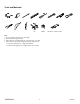
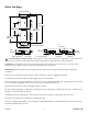
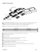
O-Rings
Retention Clips
Filters
Connectors
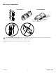
CAUTION: Risk of product damage. Do not apply excessive heat near the valve or apply ux or acids directly onto
the valve. This valve contains plastic and rubber components that will melt if heat is directly applied.
NOTE: If any outlets are not used, they must be capped or isolated using appropriate ings.
NOTE: Do not use ammoniac ux types for soldering joints as these can cause corrosion.
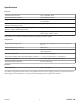
4-Outlet Valve 6-Outlet Valve
Zone 1 Outlet 1 and 2 Outlet 1, 2 and 3
Zone 2 Outlet 3 and 4 Outlet 4, 5 and 6
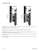
Unthread the screws securing the cover to the valve. Remove the cover and set aside.
Lift and remove the retention clips.
Remove the connectors.
Remove the O-rings.
Use needlenose pliers to remove the debris lters from the hot and cold valves.
Slide the copper or brass ing onto the inlet/outlet tube.
Solder the inlet/outlet tube to the copper or brass ings. Allow to cool completely.
Reinstall the O-ring onto the inlet/outlet tube.
For inlet tubes only: Insert the debris lters into the end of the inlet tube.
Reinstall the connectors to the valve. Secure with the retention clips. Verify that the clips are fully inserted.
Repeat for all inlet/outlet tubes as required.
Replace the cover and secure with the screws.
1430528-2-A
10 Kohler Co.