
Installation Guide


Before You Begin
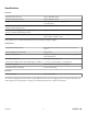
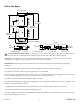
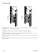
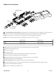
3-1/2"
(89 mm)
18-1/4"
(464 mm)
1-1/16"
(27 mm)
1-9/16" (40 mm)
4-1/2"
(114 mm)
9-3/8" (238 mm)
5-13/16" (148 mm)
8-1/4" (210 mm)
9-1/4"
(235 mm)
20-3/8"
(518 mm)
19-13/16"
(503 mm)
7/8"
(22 mm)
1-11/16" (43 mm)
5-5/16"
(135 mm)
2"
(51 mm)
3"
(76 mm)
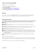
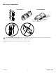
CAUTION: Risk of product damage. Do not apply excessive heat near the valve or apply ux or acids directly onto
the valve. This valve contains plastic and rubber components that will melt if heat is directly applied.
NOTICE: Do not install the valve in any location where the temperature may exceed 122°F (50°C). The valve and its
integrated power supply are rated to operate in temperatures up to 122°F (50°C).
IMPORTANT: Read these instructions and determine the locations for all required components before beginning
installation.
This valve is not intended for single-outlet use unless pairing two outlets for a high ow bath ller.
For optimum performance, dedicated water supply lines are recommended.
If the water supply is a signicant distance from the valve, it is recommended that the water supply tube size be increased
by 1/4" to oset the piping loss. If necessary, review with your Plumbing Professional.
If possible, install the valve before installing the digital control(s).
If possible, ush all piping thoroughly before installing the valve. If the pipes are ushed after the valve is installed, clean
the inlet screens before using the system.
A qualied electrician should install a 120 V GFCI electrical outlet, within the stud framing, above the valve.
If possible, install the electrical outlet before installing the valve.
This valve complies with ASME A112.18.1/CSA B125.1, ASSE 1016/ASME A112.18.1016/CSA B125.16, UL1951. This valve
is listed with IAPMO/cUPC, and UL.
Kohler Co. 5
1430528-2-A