
Installation Guide
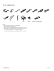


2. Prepare the Site
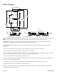
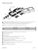
Bracket Mount
3''
(76 mm)
Min
Board Mount
3''
(76 mm)
Min
Drip Loop
Drip Loop
Drip Loop
14-1/2''
(368 mm)
Drip Loop
14-1/2''
(368 mm)
IMPORTANT! The power supply must be installed within the stud framing, near the valve. Verify that the power supply
is installed above the valve and below the electrical outlet.
NOTICE: Do not install the valve in any location where the temperature may exceed 122°F (50°C).
NOTICE: This product can be mounted on a rigid backer board or telescopic brackets (not supplied).
NOTE: Horizontal installation within a stud cavity is shown. The valve can also be mounted vertically or mounted to a
horizontal surface. Refer to the "Mounting Congurations" section.
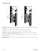
NOTE: This product is designed to t within a minimum 14-1/2" (368 mm) stud cavity. Ensure that there is a minimum 3"
(76 mm) depth clearance.
Install a 120 V GFCI electrical outlet within the stud framing, near the valve. Locate the electrical outlet above the valve
and power supply.
Kohler Co. 9
1430528-2-A