
Product Manual
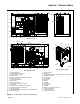
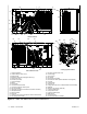
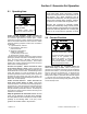
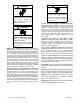
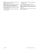
Table Of Contents

TP-6905 7/18 13Section 1 Service Views
Section 1 Service Views
6
1. Oil check (dipstick)
2. Oil fill location (on valve cover)
3. See cooling system detail
4. Exhaust outlet
5. Enclosure locking key (shipping location only)
6. Spark plugs (qty. 4)
7. Fuel pressure regulator
8. Engine ECM
9. Fuel inlet (1 in. NPT)
10. Fuel solenoid valves (qty. 2 shown)
11. Lube oil filter
12. Customer load lead access (behind panel)
13. Customer connection access panel
14. Line circuit breaker
15. Generator set master control buttons (on RDC2 controller)
16. Nameplate location
17. RDC2 controller
18. Fan fuses
19. Cooling air inlet (remove this panel to access coolant drain)
20. Access to coolant fill
21. Air-fuel mixer
22. Throttle body
23. Air cleaner
24. Battery
25. Oil drain
26. Coolant drain
27. Fans (qty. 3)
28. Radiator
29. Pressure cap (engine coolant fill)
30. Coolant overflow tube
31. Temperature sensor
32. Coolant overflow bottle
ADV-8641
14
17
23
15
28
10
9
19
16
11
12
13
3
8
1
22
24
Cooling System Detail
27
27
30
29
26
32
4
18
20
5
SERVICE SIDE
NON-SERVICE SIDE
GM90230
18
2
21
7
25
31
Figure 1-1 24RCL Service Views for Maintenance