Installation Residential/Light Commercial Generator Sets Models: 38RCL 38RCLA 48RCL 60RCL Controller: RDC2 TP-6809 6/15c
California Proposition 65 WARNING Engine exhaust from this product contains chemicals known to the State of California to cause cancer, birth defects, or other reproductive harm. Product Identification Information Product identification numbers determine service parts. Record the product identification numbers in the spaces below immediately after unpacking the products so that the numbers are readily available for future reference. Record field--installed kit numbers after installing the kits.
Table of Contents Safety Precautions and Instructions . . . . . . . . . . . . . . . . . . . . . . . . . . . . . . . . . . . . . . . . . . . . . . . . . . . . . . . . . 5 Introduction . . . . . . . . . . . . . . . . . . . . . . . . . . . . . . . . . . . . . . . . . . . . . . . . . . . . . . . . . . . . . . . . . . . . . . . . . . . . . . . 9 Service Assistance . . . . . . . . . . . . . . . . . . . . . . . . . . . . . . . . . . . . . . . . . . . . . . . . . . . . . . . . . . . . . . . . . . . . . . . . .
Safety Precautions and Instructions IMPORTANT SAFETY INSTRUCTIONS. Electromechanical equipment, including generator sets, transfer switches, switchgear, and accessories, can cause bodily harm and pose life-threatening danger when improperly installed, operated, or maintained. To prevent accidents be aware of potential dangers and act safely. Read and follow all safety precautions and instructions. SAVE THESE INSTRUCTIONS.
Battery short circuits. Explosion can cause severe injury or death. Short circuits can cause bodily injury and/or equipment damage. Disconnect the battery before generator set installation or maintenance. Remove all jewelry before servicing the equipment. Use tools with insulated handles. Remove the negative (--) lead first when disconnecting the battery. Reconnect the negative (--) lead last when reconnecting the battery.
lines with rigid lines. Use flexible sections to avoid fuel line breakage caused by vibration. Do not operate the generator set in the presence of fuel leaks, fuel accumulation, or sparks. Repair fuel systems before resuming generator set operation. Explosive fuel vapors can cause severe injury or death. Take additional precautions when using the following fuels: Propane (LPG)—Adequate ventilation is mandatory. Because propane is heavier than air, install propane gas detectors low in a room.
Connecting the battery and the battery charger. Hazardous voltage can cause severe injury or death. Reconnect the battery correctly, positive to positive and negative to negative, to avoid electrical shock and damage to the battery charger and battery(ies). Have a qualified electrician install the battery(ies). Short circuits. Hazardous voltage/current can cause severe injury or death. Short circuits can cause bodily injury and/or equipment damage.
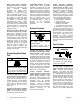
Introduction This manual provides installation instructions for the Model 38RCL, 38RCLA, 48RCL, and 60RCL generator sets. Operation manuals are available separately. See Figure 1 for an illustration of the 48RCL generator set. Information in this publication represents data available at the time of print. Kohler Co. reserves the right to change this publication and the products represented without notice and without any obligation or liability whatsoever.
Service Assistance For professional advice on generator power requirements and conscientious service, please contact your nearest authorized Kohler distributor/dealer. D Consult the Yellow Pages under the heading Generators—Electric. D Visit the Kohler Power Systems website at KOHLERPower.com. D Look at the labels and decals on your Kohler product or review the appropriate literature or documents included with the product. D Call toll free in the US and Canada 1-800-544-2444.
Section 1 Installation Instructions 1.1 Introduction Review this entire section and the Safety Precautions before starting the installation procedure. The generator set specification sheet also contains data that may be required during the installation process. The generator set and accessories must be installed by an authorized Kohler distributor/dealer or authorized representative. The installation must comply with the National Electrical Code (NEC) and local codes.
Tools Required: D Multimeter (for measuring voltage and current) D Frequency meter (may be part of multimeter) D Manometer (for measuring fuel pressure) D Torque wrench D Wrenches D Screwdrivers D Socket wrenches or nut drivers D Pliers D Safety glasses or goggles D Drill with bits and hole saw 1.2 Lifting Generator Set WARNING Unbalanced weight. Improper lifting can cause severe injury or death and equipment damage. Do not use lifting eyes.
D Lifting should only be conducted by those trained and experienced in lifting and rigging to achieve a safe and effective lift.
1.3 Location and Mounting 1.3.1 Location Factors The manufacturer recommends mounting the generator set on concrete at ground level. For above-ground installations, including roof installations, weight considerations are especially important. The building engineer must determine whether the structure can support the weight of the generator set.
1.3.3 Vibration Isolation The generator set is equipped with neoprene vibration isolators. Connections between the generator set or its mounting base and any conduits or fuel lines must include flexible sections to prevent breakage and to isolate vibration. 1.3.4 Prepare Site Choose a location that is at least 0.9 m (3 ft.) from any building or structure and near the incoming gas service. Allow a minimum of 2.4 m (8 ft.) clearance beyond the exhaust end of the generator set.
1.4 Electrical System DANGER Hazardous voltage. Will cause severe injury or death. Disconnect all power sources before opening the enclosure. WARNING Hazardous voltage. Moving parts. Can cause severe injury or death. Operate the generator set only when all guards and electrical enclosures are in place. WARNING Disconnecting the electrical load. Hazardous voltage can cause severe injury or death.
1.4.1 Electrical Connections Several electrical connections must be made between the generator set and other components of the system for proper operation. Most field-installed accessory kits include installation instructions. Comply with applicable national and local codes when installing a wiring system. For Canadian installations, refer to the Canadian Electrical Code (CEC). Row Temp.
1.4.2 Terminal Connector Torque Use the torque values shown in Figure 1-7 or Figure 1-8 for terminal connectors. Refer to UL-486A, UL-486B, and UL-486E for information on terminal connectors for aluminum and/or copper conductors. Comply with applicable national and local codes when installing a wiring system. Note: If a connector has a clamp screw such as a slotted, hexagonal head screw with more than one means of tightening, test the connector using both applicable torque values provided in Figure 1-8.
1.4.3 Ground and Neutral Connections Ground the generator set. The grounding method must comply with NEC and local codes. Connect the ground to the generator set ground lug, terminal GRD inside the junction box (see Figure 1-10). Connect the grounds for utility and low voltage connections to the ground lugs provided in the customer connection box for those specific connections (see Figure 1-10).
1.4.6 Connect AC and DC Wiring Note: Have a licensed electrician make the following electrical connections. All connections must comply with state and local codes. The generator set is equipped with a field-connection terminal block located in the access area below the junction box. Leads have been factory-installed from the junction box to the terminal block for easy field wiring.
Generator Set Connections Use separate conduit for the power cables and the low voltage communication or engine start leads. Local codes and the length of run as well as the transfer switch wire size requirements will determine the wire size needed for the AC leads. Note: Some codes require the use of a disconnect switch. Check the code requirements for your location and install a disconnect switch, if required. 1.
1.4.7 Automatic Transfer Switch Connection WARNING Hazardous voltage. Backfeed to the utility system can cause property damage, severe injury, or death. If the generator set is used for standby power, install an automatic transfer switch to prevent inadvertent interconnection of standby and normal sources of supply. Kohler Model RXT Automatic Transfer Switch The RDC2 controller is designed to control the Kohler Model RXT transfer switch as well as the generator set.
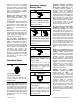
1 2 Generator Set GND 12VDC RBUS COM PWR Interface Board on the Model RXT Transfer Switch B A 4 RXT A 3 B PWR COM 4 Note: Generator set terminal block connections 3 and 4 are NOT USED with the Model RXT ATS. 1. Customer connection terminal block. See Figure 1-10 for location. Check the decal on the generator set for terminal block connections. 2. Connect one end of each cable shield to GROUND at the generator set. 3. See Figure 1-13 for cable specifications. 4.
Engine start connection for other transfer switches or a remote start/stop switch Note: Do not use the Kohlerr Model RRT transfer switch with Model RCL generator sets. Other Kohler transfer switches, including Model RDT and Model K (MPACt) transfer switches, can be used with the Kohler generator sets covered in this document. These transfer switches contain separate ATS controls that do not communicate with the RDC2 controller.
1.4.8 Communication Cable Specifications PWR and COM Connections RBUS Connections A and B For the RBUS communication connections A and B to the Model RXT transfer switch, optional PIM, and/or optional load shed kit, use 20 AWG shielded, twisted-pair communication cable. Belden #9402 (two-pair) or Belden #8762 (single-pair) or equivalent cable is recommended.
1.4.9 System Connections with Accessory Modules one programmable interface module (PIM), and/or one load shed kit. See Figure 1-14 through Figure 1-17 for connection options with up to three accessory modules. Accessory modules can include one Model RXT transfer switch, See Section 1.4.8 for cable size and length specifications. 1 2 Generator Set GND COM PWR B 3 Load Shed Kit A A B PWR COM 4 A B PWR COM RXT* A A B B PWR PWR COM COM 5 Note: See Section 1.4.
1 2 Generator Set GND COM PWR 3 B Load Shed Kit A A B PWR COM 6 4 A B PWR COM RXT* A A B B PWR PWR COM COM 5 Note: See Section 1.4.8, Communication Cable Specifications, for maximum cable lengths. * RXT transfer switch with standard or combined interface/load management board. Do not use a load shed kit with a combined interface board. 1. 2. 3. 4. 5. 6. PIM A B PWR COM Generator set terminal block. See Figure 1-10 for location.
3 1 2 COM Generator Set PWR 9402 CABLE B A 12VDC 3 RBUS COM PWR 9402 CABLE B A tp6809 Note: See Figure 1-13 for cable specifications. 1. Customer connection terminal block. See Figure 1-10 for location. Check the decal on the generator set for terminal block connections. 2. Splice 3. Connect all of the shield leads on this end to GROUND at the generator set.
Generator Set Load Shed Kit TB1 RXT ATS Notes: D See Figure 1-10 for terminal block location on generator set. Check the decal on the generator set for terminal block connections. PIM D See Figure 1-13 for maximum total cable length with 12 or 14 AWG wire. D See Figure 1-14 for communication connection (A and B, PWR and COM) details. Connect the cable shield to ground at the generator set. tp6809 Figure 1-17 Accessory Module Connections (two cable runs with one and two modules shown) 1.4.
1.5 Engine Starting Battery WARNING Sulfuric acid in batteries. Can cause severe injury or death. Wear protective goggles and clothing. Battery acid may cause blindness and burn skin. WARNING Battery electrolyte is a diluted sulfuric acid. Battery acid can cause severe injury or death. Battery acid can cause blindness and burn skin. Always wear splashproof safety goggles, rubber gloves, and boots when servicing the battery. Do not open a sealed battery or mutilate the battery case.
1.6 Fuel System WARNING Explosive fuel vapors. Can cause severe injury or death. Use extreme care when handling, storing, and using fuels. The fuel system. Explosive fuel vapors can cause severe injury or death. Vaporized fuels are highly explosive. Use extreme care when handling and storing fuels. Store fuels in a well-ventilated area away from spark-producing equipment and out of the reach of children.
1.6.1 Fuel Lines Measure the pipe length from the primary gas pressure regulator to the pipe connection on the generator set fuel inlet. Add 2.4 m (8 ft.) to the measured length for each 90 degree elbow. Use the pipe size indicated in Figure 1-18 for the total length of pipe. Gas lines. Never use fuel piping to ground electrical equipment. The gas supplier is responsible for installation, repair, and alteration to gas piping. Use Schedule 40 black-iron pipe for gas piping.
1.6.2 Gas Regulators 6. Connect the fuel supply: a. Apply pipe sealant that is approved for fuel connections to the threaded fuel connections. Gas regulators reduce high incoming fuel pressures to lower levels acceptable for engines. See the generator set specification sheet for fuel supply pressure requirements. b. Use a section of flexible fuel line to connect the fuel supply to the 1 in. NPT fuel inlet connection on the generator set.
1.6.4 Fuel Conversion Procedures FOR LP REMOVE 73A LEAD FROM FV1 AND PLUG IN 73B LEAD Note: The Integrated Electronic Pressure Regulator (IEPR) and air/fuel mixer are specially calibrated emission-control devices. Do not adjust the IEPR or the air/fuel mixer. Check the connections to the fuel solenoid valve to verify that the fuel system is set up for the type of fuel that will be used. See Figure 1-19 for the location of the fuel solenoid valve.
1.7 Cooling System WARNING 4. Operate the engine with the radiator’s pressure cap removed until the thermostat opens and the radiator upper hose becomes hot. 5. Stop the engine and allow it to cool. 6. Add coolant to the radiator to just below the overflow tube on the filler neck. See Figure 1-22. Hot coolant and steam. Can cause severe injury or death. Before removing the pressure cap, stop the generator set and allow it to cool. Then loosen the pressure cap to relieve pressure.
1.8 Prestart Installation Check 1.9 Set Exerciser Review the entire installation section. Inspect all wiring and connections to verify that the generator set is ready for operation. Check all items in the following Prestart Checklist. When power is applied to the RDC2 controller (that is, when the battery is connected), you will be prompted to set the date and time, and then to set the exerciser.
1.10 Operation Tests WARNING Hazardous voltage. Moving parts. Can cause severe injury or death. Operate the generator set only when all guards and electrical enclosures are in place. 1. Verify that all guards are in place. Install the enclosure’s end panels and nonservice side door. 1.
Notes 38 Section 1 Installation Instructions TP-6809 6/15
Section 2 Accessories 2.1 Introduction 2.2 Block Heaters Accessories are available factory-installed and/or shipped loose. Obtain the most current list of accessories from the generator set specification sheet or by contacting an authorized Kohler distributor/ dealer. Have accessories installed by your local authorized Kohler distributor/dealer or authorized representative. Follow the installation instructions provided with each kit.
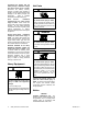
2.3 Programmable Interface Module (PIM) 2.3.2 The optional Programmable Interface Module (PIM) provides two programmable inputs and six dry contact outputsfour of which are programmable. The PIM with enclosure is shown in Figure 2-2. See TT-1584 for PIM installation and connection instructions. The PIM is mounted in a NEMA 3R aluminum enclosure, which can be mounted indoors or outdoors. See Section 1.4.
2.4 Load Management 1 Two optional load management devices are available for use with single-phase generator sets and a model RXT or RDT transfer switch: D The optional Load Shed Kit mounts inside a model 2 3 RDT or RXT transfer switch. Figure 2-4 shows the load shed assembly. D The combined interface/load management board is available for the Model RXT transfer switch. The devices provide an automatic load management system to comply with Section 702.5 of NEC 2008.
Notes 42 Section 2 Accessories TP-6809 6/15
Section 3 Generator Reconnection 3.1 Voltage Reconnection The reconnection procedure explains voltage reconnections only. Do not attempt to change the frequency (e.g. from 60 Hz to 50 Hz) in the field. The following instructions explain the reconnection of 12-lead generator sets. In all cases, follow the National Electrical Code (NEC) guidelines. Reconnect the stator leads of the generator set if a different output phase or voltage is desired. Refer to the following procedure and the connection schematics.
3.2 Four-Lead (Single-Phase) Generator Sets 3.3 12-Lead (Three-Phase) Generator Sets Figure 3-1 shows the factory connection for the singlephase 120/240 V 60 Hz generator set. Four-lead, single-phase models are not reconnectable. Three-phase, 12-lead generator sets are reconnectable to the voltages and phases shown on the generator set specification sheet.
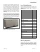
ADV-5875E-P Figure 3-2 12-Lead Generator Reconnection, 38RCL TP-6809 6/15 Section 3 Generator Reconnection 45
Note: The current transformers (CTs) shown above are not used on Model 38RCLA, 48RCL, or 60RCL generator sets equipped with the RDC2 controller.
3.4 Changing System Settings 8. Press the down arrow to step to the next setting. The RDC2 controller’s keypad and display allow the installer to check and change the generator system settings, if necessary. The system settings for each generator model are set at the factory and should not normally require changes. Check the genset system settings and change them, if necessary, after generator reconnection or controller replacement. 9. To exit, press the down arrow button until Return is displayed.
Status Displays System voltage, frequency, and phase adjustments are in the Genset System menu. Overview ----> 1.2 h Engine ----> Metering ATS ----> Configuration * Generator----> Metering Date ----> and Time Genset ----> Information Network ----> Information Genset ----> Run Time PIM Status ----> Genset System ----> Load Control ----> ATS Status ----> Event Log----> * ATS configuration appears only if a Model RXT transfer switch is connected.
Changing System Settings on the RDC2 Controller 1. Press the Select button to enter the main menu. Press: Display: Overview 1.2 h ----> Press: 2. Press the down arrow button to navigate to the Genset System menu. See Figure 3-5. Press: Display: Genset System ----> 3. Press the Select button to enter the genset system menu. Press: Display: System Voltage: 240 V 4. Press the down arrow button, if necessary, to step to the setting that you want to change. 5.
3.5 Voltage Calibration WARNING Hazardous voltage. Moving parts. Can cause severe injury or death. Operate the generator set only when all guards and electrical enclosures are in place. Testing live electrical circuits. Hazardous voltage or current can cause severe injury or death. Have trained and qualified personnel take diagnostic measurements of live circuits.
Generator ----> Metering Three-phase Single-phase Volts L1--L2: 240 V Calibrate Volts L2--L3: 240 V Calibrate Volts L3--L1: 240 V Volts: 240V Frequency: 60.0 Hz Calibrate To Calibrate Voltage: 1. Press Select when the voltage is displayed. The voltage flashes. Calibrate 2. Press the Up or Down arrow button to change the setting. 3. Press the Select button to save the setting. Frequency: 60.0 Hz 4. Press the down arrow button to move to the next menu.
3.5.2 Calibration Using SiteTech Voltage calibration factors can be adjusted using SiteTech software to calibrate the RDC2 controller. Connect a personal computer (laptop) to the controller using a USB cable and follow this procedure to use Kohlerr SiteTecht software to calibrate the controller. The voltage calibration factors are located in the Genset Calibration group in SiteTecht. Find the parameter labelled Genset Calibration Factor Voltage, L1--L2. See Figure 3-9.
1 # 1.
Notes 54 Section 3 Generator Reconnection TP-6809 6/15
Section 4 Diagrams and Drawings This section contains dimension drawings, wiring diagrams, and schematics for the enclosed generator set. Figure 4-1 lists the drawing numbers and page numbers. Drawings are arranged in numerical order on the following pages. 38RCL See the generator set Operation Manual for service views, if necessary.
Figure 4-2 Schematic, 38RCLA/48RCL/60RCL Alternator, ADV-6957 56 Section 4 Diagrams and Drawings TP-6809 6/15
Figure 4-3 Schematic Diagram, 38RCLA/48RCL/60RCL Generator Set, ADV-8061, Sheet 1 of 2 TP-6809 6/15 Section 4 Diagrams and Drawings 57
Figure 4-4 Schematic Diagram, 38RCLA/48RCL/60RCL Generator Set, ADV-8061, Sheet 2 of 2 58 Section 4 Diagrams and Drawings TP-6809 6/15
Figure 4-5 Schematic Diagram, 38RCL Generator Set, ADV-8484, Sheet 1 of 3 TP-6809 6/15 Section 4 Diagrams and Drawings 59
Figure 4-6 Schematic Diagram, 38RCL Generator Set, ADV-8484, Sheet 2 of 3 60 Section 4 Diagrams and Drawings TP-6809 6/15
Figure 4-7 Schematic Diagram, 38RCL Generator Set, ADV-8484, Sheet 3 of 3 TP-6809 6/15 Section 4 Diagrams and Drawings 61
Figure 4-8 Dimension Drawing, 38RCL/38RCLA/48RCL/60RCL, ADV-8545, Sheet 1 of 2 62 Section 4 Diagrams and Drawings TP-6809 6/15
Figure 4-9 Dimension Drawing, 38RCL/38RCLA/48RCL/60RCL, ADV-8545, Sheet 2 of 2 TP-6809 6/15 Section 4 Diagrams and Drawings 63
Figure 4-10 Wiring Diagram, 38RCLA/48RCL/60RCL Alternator, GM35943 64 Section 4 Diagrams and Drawings TP-6809 6/15
Figure 4-11 Wiring Diagram, 38RCLA/48RCL/60RCL Generator Set, GM79871, Sheet 1 of 2 TP-6809 6/15 Section 4 Diagrams and Drawings 65
Figure 4-12 Wiring Diagram, 38RCLA/48RCL/60RCL Generator Set, GM79871, Sheet 2 of 2 66 Section 4 Diagrams and Drawings TP-6809 6/15
Figure 4-13 Wiring Diagram, 38RCL Generator Set, GM85226, Sheet 1 of 2 TP-6809 6/15 Section 4 Diagrams and Drawings 67
Figure 4-14 Wiring Diagram, 38RCL Generator Set, GM85226, Sheet 2 of 2 68 Section 4 Diagrams and Drawings TP-6809 6/15
Appendix A Abbreviations The following list contains abbreviations that may appear in this publication. A, amp ABDC AC A/D ADC adj. ADV Ah AHWT AISI ALOP alt. Al ANSI AO APDC API approx. APU AQMD AR AS ASE ASME assy. ASTM ATDC ATS auto. aux. avg. AVR AWG AWM bat. BBDC BC BCA BCI BDC BHP blk. blk. htr. BMEP bps br. BTDC Btu Btu/min. C cal. CAN CARB CAT5 CB CC cc CCA ccw. CEC cert.
kg/cm2 kilograms per square centimeter kgm kilogram-meter kg/m3 kilograms per cubic meter kHz kilohertz kJ kilojoule km kilometer kOhm, k kilo-ohm kPa kilopascal kph kilometers per hour kV kilovolt kVA kilovolt ampere kVAR kilovolt ampere reactive kW kilowatt kWh kilowatt-hour kWm kilowatt mechanical kWth kilowatt-thermal L liter LAN local area network L x W x H length by width by height lb.
Notes TP-6809 6/15 71
KOHLER CO. Kohler, Wisconsin 53044 Phone 920-457-4441, Fax 920-459-1646 Kohler Power Systems Asia Pacific Headquarters 7 Jurong Pier Road Singapore 619159 Phone (65) 6264-6422, Fax (65) 6264-6455 TP-6809 6/15c E 2012, 2013, 2015 by Kohler Co. All rights reserved. For the nearest KOHLER authorized installation, service, and sales dealer in the US and Canada: Call 1-800-544-2444 or visit KOHLERPower.