
Installation Guide


TP-6809 6/15 19Section 1 Installation Instructions
1.4.3 Ground and Neutral Connections
Ground the generator set. The grounding method must
comply with NEC and local codes. Connect the ground
to the generator set ground lug, terminal GRD inside the
junction box (see Figure 1-10). Connect the grounds for
utility and low voltage connections to the ground lugs
provided in the customer connection box for those
specific connections (see Figure 1-10).
Various regulations and site configurations including the
National Electrical Code (NEC), local codes, and the
type of transfer switch used in the application determine
the grounding of the neutral at the alternator. NEC 2002
Section 250.20 is one example that has a very good
explanation of the neutral grounding requirements for
generator sets.
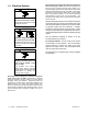
Generator sets are shipped with the generator set
neutral attached to the alternator in the junction box. At
installation, the neutral can be grounded at the
generator set or lifted from the ground stud and isolated
if the installation requires an ungrounded neutral
connection at the alternator. The generator set will
operate properly with the neutral either bonded to
ground or isolated from ground at the alternator.
1.4.4 Battery Chargers
An engine-driven, battery-charging alternator charges
the battery whenever the generator set operates.
Engine-driven systems can quickly restore the charge
used in a normal cranking cycle.
When the engine is not operating, a very low charge rate
from an AC-powered battery charger is usually sufficient
to maintain a full charge on the batteries. The RDC2
controller contains a built-in battery charger to maintain
the generator set’s engine starting battery. Be sure to
provide AC power for the integral battery charger as
instructed in Section 1.4.5.
1.4.5 Power Supply
Power must b e supplied to the generator set location for
the battery charger and optional accessories. The
power source must comply with both state and local
codes. The power to the accessories must be available
at all times, i.e. the circuit must be powered by the utility
source and backed up by the generator set.
Connect power to the leads in the utility power
connection area shown in Figure 1-10. See the wiring
diagrams in Section 4 for connection details. See
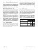
Figure 1-9 for the power requirements for the battery
charger and accessories.
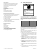
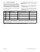
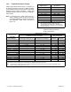
Equipment
Power R equirement
Watts Amps Volts
Battery charger (standard,
integral to RDC2 controller)
50 0.42 120
Block heater (optional)
1500
12.5 120
6.3 240
Battery heater (optional) 80 0.7 120
Figure 1-9 Power Requirements