
Installation Guide


TP-6809 6/1520 Section 1 Installation Instructions
1.4.6 Connect AC and DC Wiring
Note: Have a licensed electrician make the following
electrical connections. All connections must
comply with state and local codes.
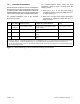
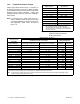
Size the wire according to the length of run and 115% of
the circuit current (amperage) based on 75_Cwire
rating or less as directed by the National Electrical
Coder (NEC) in ANSI/NFPA 70. See Section 1.4.1 for
additional information about wire selection.
The generator set is equipped with a field-connection
terminal block located in the access area below the
junction box. Leads have been factory-installed from
the junction box to the terminal block for easy field
wiring.
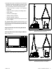
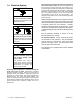
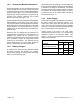
See Figure 1-10. Make all AC and DC customer
connections inside the customer connection box. Do
not remove the end panel or make connections inside
the junction box. Refer to the wiring diagrams in
Section 4.
1. Access panel (remove to access connections)
2. 120VAC connection leads and ground screw
3. Installer to punch access openings
4. Low voltage connection terminal block
5. Ethernet cable connection for OnCue Plus
6. Ground (GRD) lug
7. Load lead access opening
8. Load lead connections to line circuit breaker
9. Neutral lug
GM78527
1
69
4
2
3
Connection details
Access panel removed.
8 7 5
Figure 1-10 Generator Set Connections