
Installation Guide


Layout Options
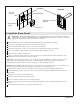
1. Review the Layout
CAUTION: Risk of personal injury. Do not install the Steam Control User Interface outside the
steam enclosure. The User Interface must be installed within the enclosure to allow the sensors to
regulate the temperature and control the flow of steam.
CAUTION: Risk of scalding. Do not locate the steam head near a seat or bench, as the steam head
is hot during operation and may scald the user if touched.
NOTICE: The user interface should be mounted on the wall opposite the steam head. The steam head
should always be located as far away from the seating area as possible.
NOTICE: Locate the steam head 6″ (152 mm) above the floor and a minimum of 4-1/2″ (114 mm) from
the threshold.
Steam Generator
Control Cable Input
Drain/Spill Pan
Drip Loop
Steam Head and
Housing Assembly
Connector, RJ12 Double Female (Assembled to Control Cable)
Control Cable
50' (15.2 m) White, Crossover
UIC
Steam Head and
Housing Assembly
Cable Data 6P/6C
78" (1981 mm)
Black, Straight Through
Coupler 3-Way Straight
Cable Data 6P/6C
10" (254 mm)
Black, Straight Through
Drip Loop
Steam Generator
Control Cable
Input
Drain/Spill Pan
Drip Loop
Steam Head and
Housing Assembly
Connector, RJ12 Double
Female(Assembled to
Control Cable)
Control Cable
50' (15.2 m)
White, Crossover
UIC
Kohler Co. 3 1230489-2-C