OWNER'S MANUAL COMMAND PRO CH940-CH1000 HORIZONTAL CRANKSHAFT 1
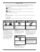
Safety Precautions To ensure safe operations please read the following statements and understand their meaning. Also refer to your equipment owner's manual for other important safety information. This manual contains safety precautions which are explained below. Please read carefully. WARNING Warning is used to indicate the presence of a hazard that can cause severe personal injury,death, or substantial property damage if the warning is ignored.
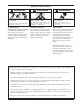
Safety Precautions (Cont.) WARNING Accidental Starts can cause severe injury or death. Disconnect and ground spark plug lead before servicing. Accidental Starts! Disabling engine. Accidental starting can cause severe injury or death. Before working on the engine or equipment, disable the engine as follows: 1) Disconnect the spark plug lead(s). 2) Disconnect negative (-) battery cable from battery. WARNING Carbon Monoxide can cause severe nausea, fainting or death.
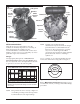
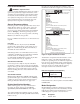
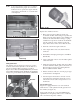
Air Cleaner Lifting Point Oil Filter Throttle Control Lever Choke Control Lever Carburetor Oil Fill Spark Plug Fuel Pump Lifting Strap Dipstick Electric Starter Cylinder Shrouds Blower Housing Oil Drain Plugs Screen Figure 1. Typical Command PRO Horizontal Shaft Engine. Using the proper type and weight of oil in the crankcase is extremely important. So is checking oil daily and changing oil regularly. It is also recommended that a consistent brand of oil be used.
Fuel Recommendations Record your engine identification numbers on the identification label below (Figure 4) for future reference. WARNING: Explosive Fuel! Gasoline is extremely flammable and its vapors can explode if ignited. Store gasoline only in approved containers, in well ventilated, unoccupied buildings, away from sparks or flames. Do not fill the fuel tank while the engine is hot or running, since spilled fuel could ignite if it comes in contact with hot parts or sparks from ignition.
Operating Instructions Also read the operating instructions of the equipment this engine powers. Pre-Start Checklist • Check oil level. Add oil if low. Do not overfill. • Check fuel level. Add fuel if low. • Check cooling air intake areas and external surfaces of engine. Make sure they are clean and unobstructed. • Check that the air cleaner components and all shrouds, equipment covers, and guards are in place and securely fastened.
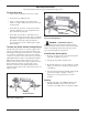
If the starter does not turn the engine over, shut off starter immediately. Do not make further attempts to start the engine until the condition is corrected. Do not jump start using another battery (refer to Battery on this page). See your Kohler Engine Service Dealer for service assistance. Throttle Lever Choke Lever Figure 7. Location of Control Levers. Control Lever Knobs 3. For a Cold Engine – Gradually return the choke control to the OFF position after the engine starts and warms up.
WARNING: Hot Parts! Engine components can get extremely hot from operation. To prevent severe burns, do not touch these areas while the engine is running, or immediately after it is turned off. Never operate the engine with heat shields or guards removed. Engine Speed NOTE: Do not tamper with the governor setting to increase the maximum engine speed. Overspeed is hazardous and will void the engine warranty. The maximum allowable high idle speed for these engines is 3900 RPM, no load.
Pressure Switch Oil Fill Dipstick Figure 9. Dipstick and Oil Fill. 4. Remove the dipstick and check the oil level. The oil level should be up to, but not over, the F mark on the dipstick. See Figure 10. Figure 11. Oil Sentry™ Pressure Switch. NOTE: Make sure the oil level is checked BEFORE EACH USE and is maintained up to the F mark on the dipstick. This includes engines equipped with Oil Sentry™ systems.
NOTE: To prevent extensive engine wear or damage, always maintain the proper oil level in the crankcase. Never operate the engine with the oil level below the L mark or over the F mark on the dipstick. Figure 15. Optional Remote Mounted Oil Filter. Replace the oil filter as follows: Drain Plug Figure 12. Oil Drain Plug (Starter Side). 1. Before removing the oil filter, clean the area around the oil filter and housing to keep dirt and debris out of the engine. Remove the old filter.
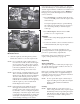
To access and service the oil cooler, remove the top mounting screw and loosen the two side screws, then lift off the No. 2 side cylinder shroud. If required, remove the two screws holding the oil cooler to the blower housing. Pull the cooler away from the blower housing. Clean both sides of the cooler with a brush as shown in Figures 17 and 18, or with compressed air. After cleaning, reattach the oil cooler to the lower blower housing with the two mounting screws.
Flat Air Cleaner The flat air cleaner has a replaceable, high density paper air cleaner element. Some engines are also equipped with an oiled, foam precleaner which surrounds the paper element. See Figure 23. Paper Element Cover Knobs Air Cleaner Cover Inner Element Precleaner Figure 21. Removing Elements. 3. After the paper element is removed, check the condition of the inner element.
Service Paper Element Every 150 hours of operation (more often under extremely dusty or dirty conditions) replace the paper element. 1. Loosen the cover retaining knobs and remove the cover. 2. Rotate the element latch to release the element. 3. Remove the paper element with precleaner. 4. Remove the precleaner (if so equipped) from the paper element. Service the precleaner as described above. 5. Do not wash the paper element or use pressurized air, as this will damage the element.
Battery Charging WARNING: Explosive Gas! Batteries produce explosive hydrogen gas while being charged. To prevent a fire or explosion, charge batteries only in well ventilated areas. Keep sparks, open flames, and other sources of ignition away from the battery at all times. Keep batteries out of the reach of children. Remove all jewelry when servicing batteries. Before disconnecting the negative (-) ground cable, make sure all switches are OFF.
2. Place the throttle control into the idle or slow position. Adjust the low idle speed to 1200 RPM*. Adjust Carburetor Low Idle Speed (RPM) and Governed Idle Adjustment 1. Low Idle Speed (RPM) Setting: Place the throttle control into the idle or slow position. Hold the governor lever away from carburetor so the throttle lever is against the Idle Speed (RPM) Adjustment Screw of carburetor. See Figure 26.
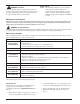
Troubleshooting When troubles occur, be sure to check the simple causes which, at first, may seem too obvious to be considered. For example, a starting problem could be caused by an empty fuel tank. Some common causes of engine troubles are listed in the following table. Do not attempt to service or replace major engine components, or any items that require special timing or adjustment procedures. Have your Kohler Engine Service Dealer do this work.
Specifications Model: ................................................................... CH940 .................... CH960 .................. CH980 .............................. CH1000 Bore: ................................................ mm (in.) ..... 90 (3.54) ................. 90 (3.54) ............... 90 (3.54) ........................... 90 (3.54) Stroke: ............................................. mm (in.) ..... 78.5 (3.1) ................ 78.5 (3.1) .............. 78.5 (3.1) ....................
KOHLER CO. FEDERAL AND CALIFORNIA EMISSION CONTROL SYSTEMS LIMITED WARRANTY SMALL OFF-ROAD AND CLASS 1 LSI ENGINES The U.S. Environmental Protection Agency (EPA), the California Air Resources Board (CARB), and Kohler Co. are pleased to explain the Federal and California Emission Control Systems Warranty on your off-road equipment engine. In California beginning in 2006, "emissions" means both exhaust and evaporative emissions.
Listed below are the parts covered by the Federal and California Emission Control Systems Warranty. Some parts listed below may require scheduled maintenance and are warranted up to the first scheduled replacement point for that part.
FORM NO.: 62 590 01-A ISSUED: 1/07 REVISED: 4/09 LITHO IN U.S.A. FOR SALES AND SERVICE INFORMATION IN U.S. AND CANADA, CALL 1-800-544-2444 KohlerEngines.com ENGINE DIVISION, KOHLER CO.