
Vertical Crankshaft Service Manual

10.13
Section 10
Inspection and Reconditioning
10
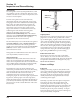
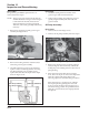
Figure 10-16. Oil Pump, Oil Pickup, and Relief
Valve (Original Style).
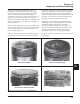
Figure 10-17. Oil Pump, Plastic Oil Pickup, and
One-Piece Relief Valve (Later Style).
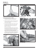
Inspection
Inspect the oil pump housing, gear, and rotors for
nicks, burrs, wear, or any visible damage. If any parts
are worn or damaged, replace the oil pump.
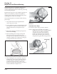
Inspect the oil pressure relief valve piston. It should be
free of nicks or burrs.
Check the spring for wear or distortion. The free
length of the spring should be approximately 47.4 mm
(1.8 in.). Replace the spring if it is distorted or worn.
See Figure 10-18.
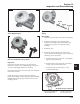
Figure 10-18. Oil Pressure Relief Valve Piston and
Spring.
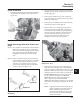
Reassembly
1. Install the pressure relief valve piston and spring.
2. Install the oil pickup to the oil pump body.
Lubricate the O-Ring with oil and make sure it
remains in the groove as the pickup is being
installed.
3. Install the rotor.
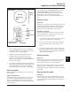
4. Install the oil pump body to the oil pan and
secure with the two hex flange screws. Torque the
hex flange screws as follows:
a. Install fastener into location No. 1 and lightly
tighten to position pump.
b. Install fastener into location No. 2 and fully
torque to the recommended value.
c. Torque fastener in location No. 1 to the
recommended value.
Piston
Spring
Roll Pin
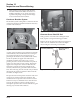
First Time Installation: 10.7 N·m (95 in. lb.)
All Reinstallations: 6.7 N·m (60 in. lb.)
Oil Pump Torque Sequence